BENNING IT 130 Measurements
- 45 -
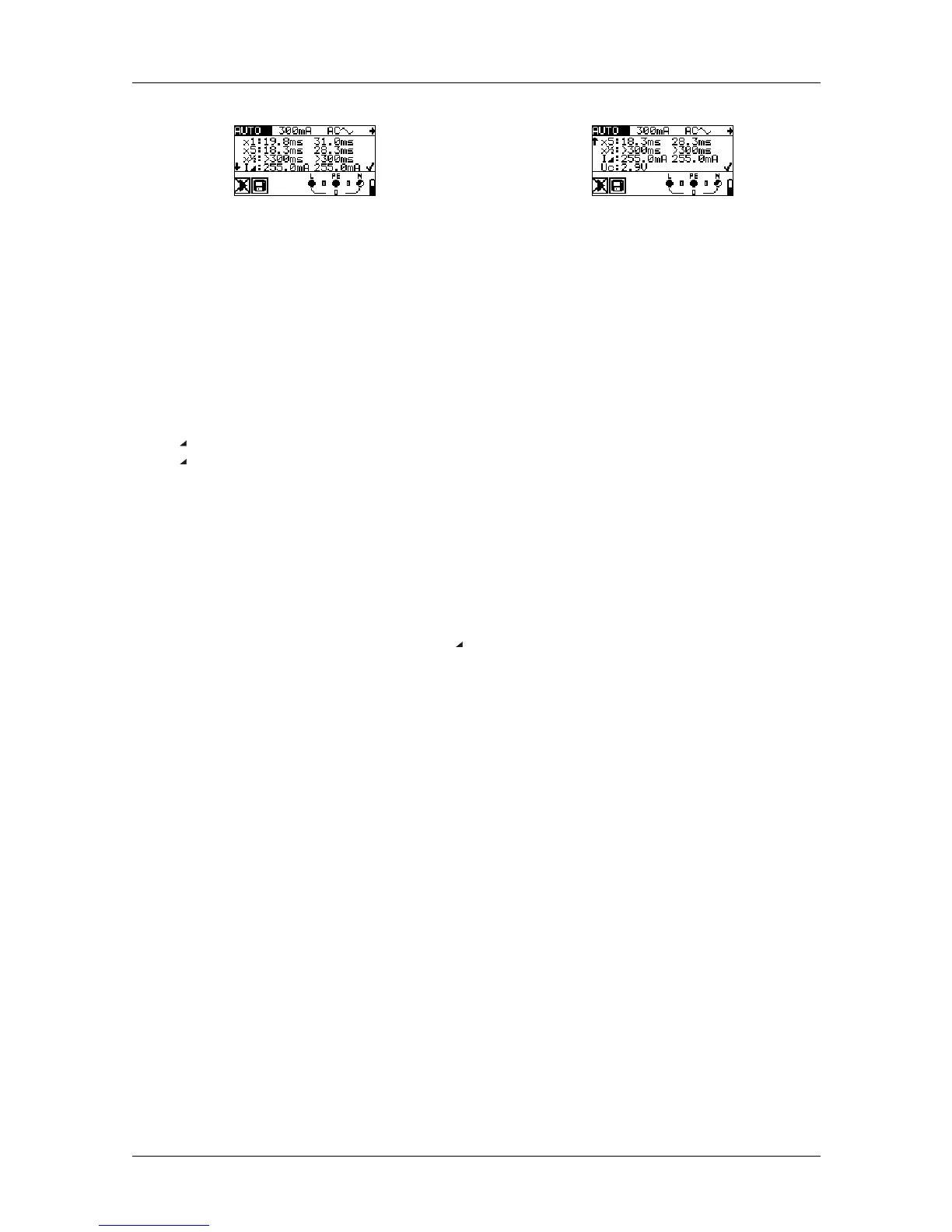
Top
Bottom
Figure 5.22: The "HELP" key toggles between the upper
and the lower part of the result field.
Results displayed:
x1 .........step 1 tripping time (I
∆
=I
∆N
, 0º)
x1 .........step 2 tripping time (I
∆
=I
∆N
, 180º)
x5 .........step 3 tripping time (I
∆
=5×I
∆N
, 0º)
x5 .........step 4 tripping time (I
∆
=5×I
∆N
, 180º)
x½........step 5 tripping time (I
∆
=½×I
∆N
, 0º)
x½........step 6 tripping time (I
∆
=½×I
∆N
, 180º)
I ...........step 7 tripping current (0º)
I ...........step 8 tripping current (180º)
Uc ........contact voltage for nominal value I
∆N
Notes:
The automatic test will be stopped immediately, if any invalid condition is detected, e.g.
exceedance of the maximum admissible contact voltage or a tripping time outside the
admissible range.
During the automatic testing of RCDs of the types A and F with nominal tripping
differential currents of 300 mA, 500 mA and 1000 mA, the test of 5×I
∆
N will not be
carried out. In this case, the test shall be passed, if all other test have been passed.
The tripping current measurement (I , steps 7 and 8) is not carried out for selective
RCDs.