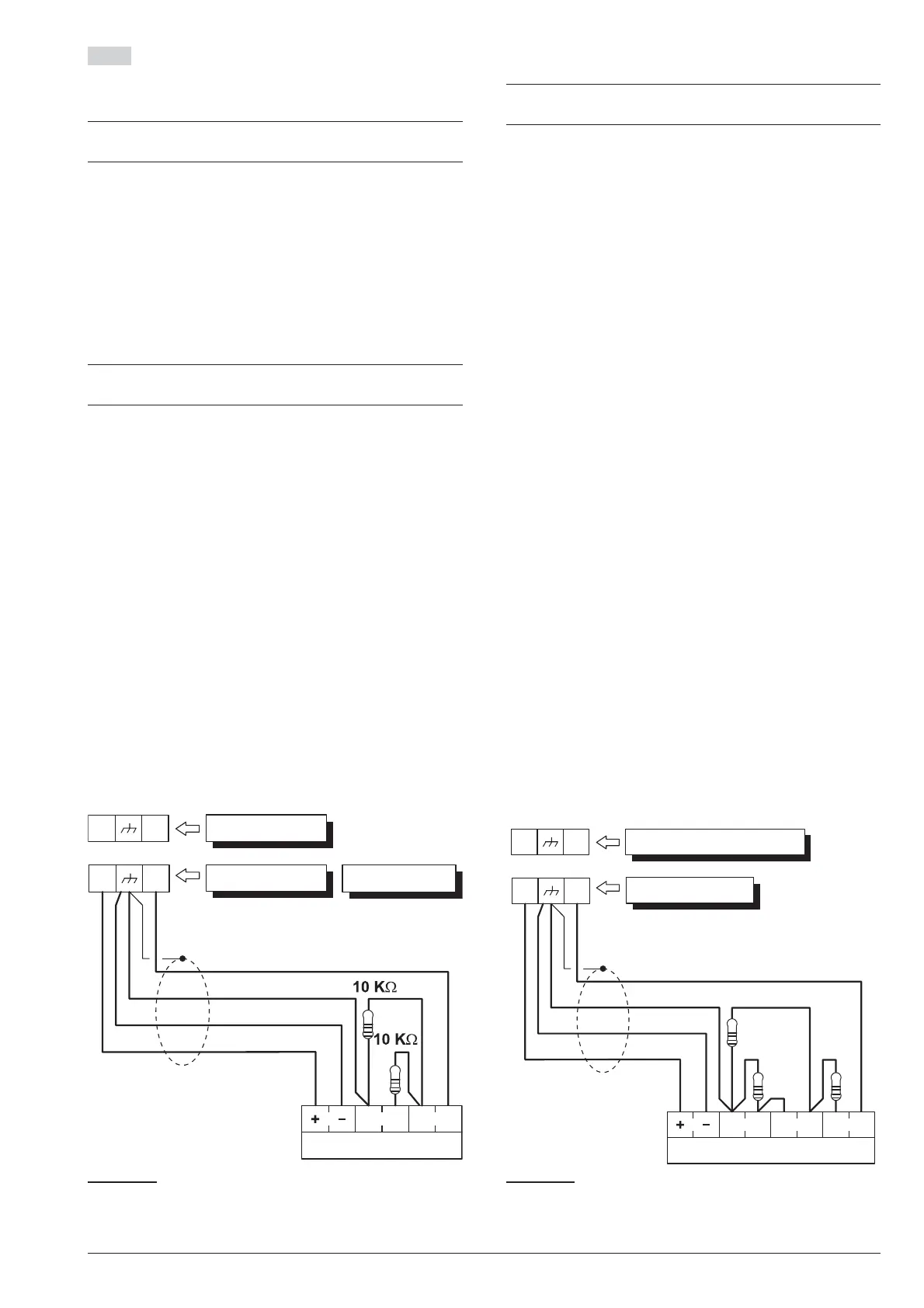
DEOL The wiring diagram in Fig. 12 illustrates the con
-
nection of a detector to a Input Line (Zone) with DEOL
supervision.
+
The 10 KW resistors must be connected to the last
detector of the zone.
DEOL Supervision will allow the Control Panel to detect
zone Alarm, Tamper and Short-circuit:
Ø
the zone will hold Standby status whilst connected to
negative via a 5 KW resistor (i.e. using two 10 KW re
-
sistors connected in parallel);
Ø
the zone will trigger short-circuit when connected to
negative;
Ø
the zone will trigger Tamper when open;
Ø
the zone will trigger Alarm under all other conditions.
+
Zones with DEOL supervision can detect and sig
-
nal Alarm and Tamper by means of just two wires.
n
Connection of Grade 3 detectors
3
This type of connection is only possible with Grade 3
Control Panels and Input/Output Expanders.
The wiring diagram in Figure 13 illustrates the connec
-
tion of a Grade 3 detector to a Input Line (Zone) with
Triple End of Line supervision (refer to “PROGRAM
-
MING FROM THE PC > Zones”).
In addition to the contacts for signalling tampering and
alarms, Grade 3 detectors are equipped with a contact
that is normally closed for reporting faults, such as
masking (Fault in Figure 13).
Tripe End of LIne Supervision will allow the Control
Panel to detect zone Alarm, Tamper, Fault and
Short-circuit:
Ø
the zone will hold Standby status whilst connected to
negative via a 2,2 KW resistance;
Ø
the zone will trigger short-circuit when connected to
negative;
Ø
the zone will trigger Tamper when open;
Ø
the Zone will trigger Fault when connected to nega
-
tive with a resistance of 24.2 KW (i.e. the series of the
resistors from 2.2 KW and 22 KW);
Ø
the Zone will trigger Alarm when connected to nega
-
tive with a resistance of 8.2 KW (i.e. series of the
2.2 KW resistor with the parallel of the resistors from
22 kW and 8.2 kW).
30 Expandable Hybrid Control Panel
Detector
N. C. A.
L1
+F
S.
Panel
Keypad
Input Expander
T1
+F
Figure 12 Connecting a Detector to a zone with DEOL
supervision.
Grade 3 Detector
N. C. A.Fault
L1
+F
S.
Grade 3 Panel
Grade 3 Input Expander
T1
+F
2,2 KW
22 KW
8,2 KW
Figura 13 Connecting a Detector to a zone with Triple
End of Line Supervision.



 To Next Page