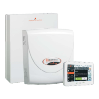
Connecting the AS100 Audio Station
The AS100 (accessory item) is a 2-way audio station
that include a speaker and a microphone.
By means the AS100:
Ø
the Installer can record and playback the Voice Mes
-
sages (refer to “2.1 Voice Message Recording” in the
“KEYPAD OPERATION” section);
Ø
the User can perform some audio functions by a re
-
mote telephone (refer to “OPERATING THE
SYSTEM FROM A TELEPHONE” in the User Man
-
ual);
Ø
the user can have an audio feedback on the security
system status (refer to “Event and Actions” in the
“PROGRAMMING FROM THE PC” section).
Ø
the Central Station operator can perform an audio
verification of the alarm event.
+
This Control Panel support ONE AS100.
Refer to the diagram in Figure 21 for the connection of
the AS100 to the Control Panel’s Main Board.
A
The audio station AS100 is NOT certified
IMQ-SECURITY SYSTEMS and therefore does
not conform to the EN50131-1 and EN50131-3
standards.
Power Supply
!
In order to comply with the Safety regulations
in force, the Mains must be equipped with a bi
-
polar isolating device for protection against
over voltage and short-circuit to Earth, in
-
stalled outside the control panel and easily ac
-
cessible, with minimum contact distance of
3 mm (e.g. automatic isolating switch).
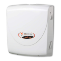
The ABSOLUTA is powered from the Mains (230V/50 Hz)
through a Switching power supply, located inside the cab
-
inet. The cabinet can also house a backup battery (not in
-
cluded) for power backup during Mains failure.
Mains failure will be signalled by the:
Ø
OFF status of indicator on the Power Supply;
Ø
ON status of the G indicator on Keypads;
Ø
Warning Mains failure event.
+
The Warning Mains failure event will be signalled
after the programmed delay (refer to “Filter Times”
in the “PROGRAMMING FROM PC” section).
The panel reports a fault when the output voltage drops
below 11.2 V, with:
Ø
ON status of the G indicator on Keypads;
Ø the message Panel low Vout on the LCD
Keypads, in View Signals mode.
The Control Panel will monitor the battery at all times,
(refer to Static Test and Dynamic Test).
Static Test The Static Test monitors the battery
charge during Mains failure. Low battery status (below
11.4 V) will be signalled by the:
Ø Low battery event;
Ø ON status of the G indicator on Keypads.
If this occurs, the Mains power must be restored before
the battery empties, otherwise, the system will shutdown.
Low battery restoral (over 12.3 V) will be signalled by:
Ø
the end of the Warning low battery event;
Ø
The G indicator on Keypad turn OFF only after the
reset of all events (the events stay in memory).
+
The Control Panel automatically shuts down when
the battery voltage drops below 9.6 V to protect the
battery from permanent damage.
Dynamic Test The Dynamic Test monitors the oper
-
ating capacity of the battery. A failed test (battery does
not meet the Test requirements) will be signalled by the:
Ø
Warning power trouble event;
Ø
ON status of the G indicator on Keypads.
If this occurs, the backup battery must be replaced im
-
mediately, otherwise, the system will be unable to func
-
tion in the event of Mains failure (black-out).
Battery trouble restoral will be signalled by the:
Ø
end of the Warning power trouble event;
Ø
The G indicator on Keypad turn OFF only after the
reset of all events (the events stay in memory).
ABSOLUTA INSTALLING 35
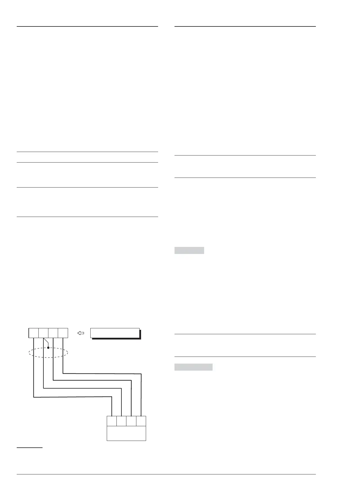
S M
B
R
AS100
RED
Control Panel
BLKSPKMIC
Yellow
White
Black
Red
Figure 21 Connecting the AS100 to the Control Panel.