n
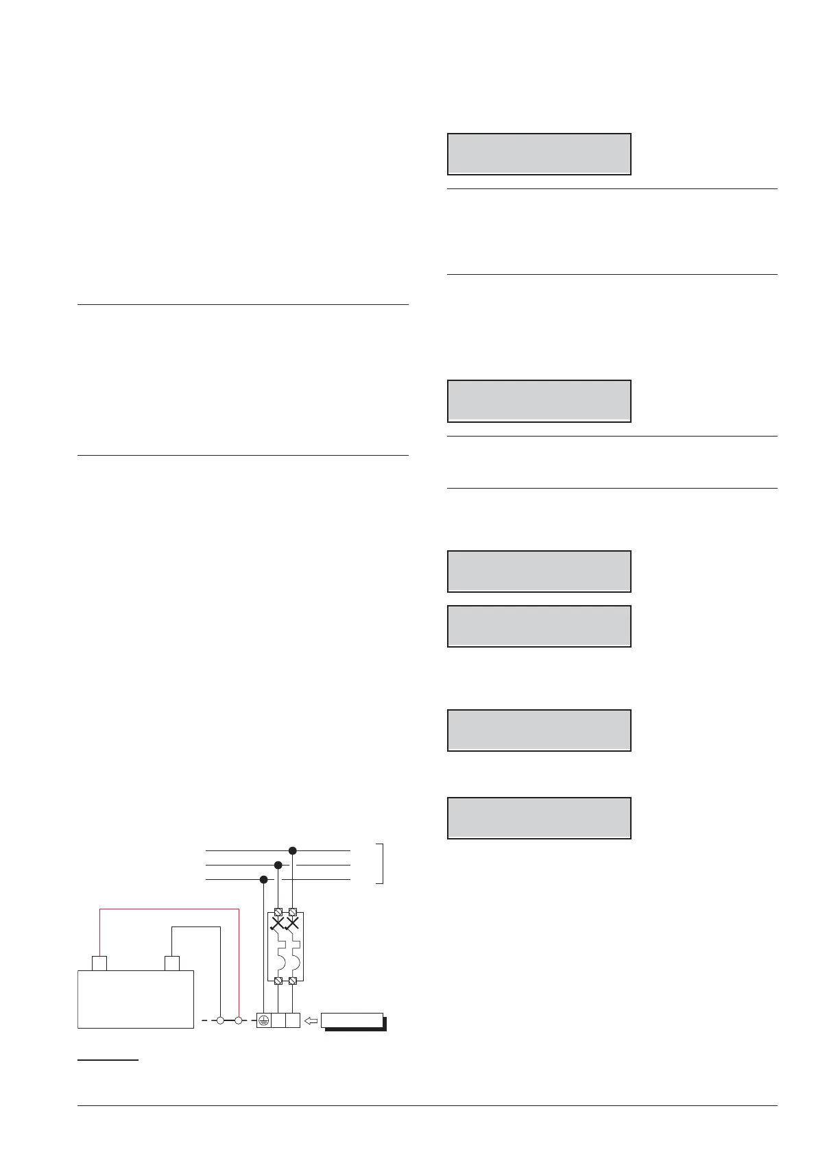
Power connection
Work carefully through the following steps (refer to
“Parts Identification”).
1. Locate the backup battery on its housing 33.
2. Connect the backup battery to the connector 13 on
the Main Board, by means the cable 30.
3. Connect the Earth wire to the [Q] terminal on the
power supply terminal board.
4. Connect the Neutral wire to terminal [N], and the
Line wire to terminal [L] on the power supply termi
-
nal board.
+
The Control Panel Tamper Switch is enabled by
the initial closure of the Control Panel. Therefore, it
cannot trigger a Tamper on Panel event on first
power up. Likewise, if the Panel is opened during a
programming session (via Keypad or computer),
the Tamper switch will be inhibited thus unable to
trigger a Tamper on Panel event until the Pro
-
gramming session ends, and the Panel is closed
again.
n
Power disconnection
To disconnect the power, proceed as described below
(see “IDENTIFICATION OF PARTS” on pages 15, 16
and 17).
1. Disconnect the Neutral [N] and Line [L] on the
Power-Supply terminal board.
2. Disconnect the Earth wire [Q].
3. Wait for the control panel to signal the lack of main
voltage, with:
Ø
the keypad light indicator G;
Ø
the message Panel NO 220v on the keypads, in
view signals mode (see “View Signals” in the USER
MANUAL).
4. Disconnect backup battery cable 30 from connec
-
tor 13 of the Motherboard.
n
Auto-configuration (Wizard setup)
Each time you power up the control panel, the LCD
keypads will show the following message, for approxi
-
mately 15 second, indicating that the Control Panel is
performing the Auto-configuration:
CALL
SERVICE
+
If you are performing the Hardware Default, the LCD
Keypads show the message “RemoveJumpPCLInk”
that remember to you to remove the short circuit on
the PC-LINK connector (refer to “Hardware Default”
for further details).
During this phase the Control Panel will enroll the BPI
Bus peripherals.
Termination of this phase will be indicated on the LCD
Keypads as follows:
Presse,Presiona
Premi,Push ENTER
+
Press ENTER once and wait a few moments for the
next message to appear: the time taken will depend
on the number of devices connected to the BPI bus.
1. When you press ENTER, the display will show the
available languages:
Mod. Lingua 1/9
1=Italiano
Modify Lang. 2/9
2=English
2. Select the required language by enter the relative
number:
Panel ID
0000
3. Enter the Panel ID then press ENTER:
Kb=01 Kr=00 Al=0
Ei=00 Eo=00 OK?
The keypad shows the enrolled BPI devices as follow:
Ø
Kb are the Keyboards;
Ø
Kr are the Key readers;
Ø
Al are the Power Stations;
Ø
Ei are the Input Expanders;
Ø
Eo are the Output Expanders.
4. Press ENTER if the display configuration is right
and go to the next step, or check the connection
and the address of the missed BPI peripherals,
then press OFF and ESC, and go back to the step
1.
36 Expandable Hybrid Control Panel
L
Panel
N
Automatic
Isolating
Switch
+
–
Backup Battery
Line
Neutral
Earth
230 V
50 Hz
Figure 22 Connecting the Mains power.



 To Next Page