Connecting Alarm Signalling Devices
A
The panel, to complies the EN50131-1 and
EN50131-3 standards, supports the following noti
-
fication options:
A) 2 sirens with remote power supply + panel
built-in telephone communicator;
B) 1 self-powered siren + panel built-in telephone
communicator;
C) panel built-in telephone communicator + exter
-
nal telephone communicator with at least ATS-1
grade performance, according with the EN50131
and EN50136-1-1-1 standards (Grade 2 Control
Panels only);
D) external telephone communicator with at least
ATS-3 grade performance, according with the
EN50131 and EN50136-1-1-1 standards.
The ABSOLUTA Control Panel is equipped with three
outputs to connect the Alarm Signalling Devices:
Ø
the terminals NC, COM, NO, +N and +A are relevant
to the output no. 1;
Ø
the terminal O1 is relevant to the output no. 2;
Ø
the terminal O2 is relevant to the output no. 3.
A
At default, The O2 open-collector output is active in
case of trouble. If this setting is not changed, to
maintain compliance with the EN50131-1 and
EN50131-3 standards, you must NOT connected
additional and self-powered sirens to this output.
Alternatively, you can connect the Alarm Signalling De-
vices to:
Ø terminals T1, T2, T3 and T4 of the Control Panel, if
programmed as Outputs;
Ø terminals T1, T2, T3, T4, T5 and T6 of the Input/Out-
put Expander M-IN/OUT, depending on the pro-
grammed operating mode (refer to the M-IN/OUT’s
instructions for more information).
Alarm Signalling Devices, such as: Self-Powered Si
-
rens, Indoor Sirens, Telephones Diallers, etc., can be
classified as follows:
Ø
Intrinsic Security Devices (e.g. Self-Powered Si
-
rens) activated by voltage failure on the respective
terminal;
Ø
Positive Alarm Line devices (e.g. Indoor Sirens) ac
-
tivated by positive (12 V) on the respective terminal;
Ø
Negative Alarm Line devices activated by negative
(0 V) on the respective terminal;
Ø
Supervised Alarm Line devices activated by im
-
pedance unbalance on the respective terminal.
The wiring diagram depend on the Alarm Signalling De
-
vice to connect.
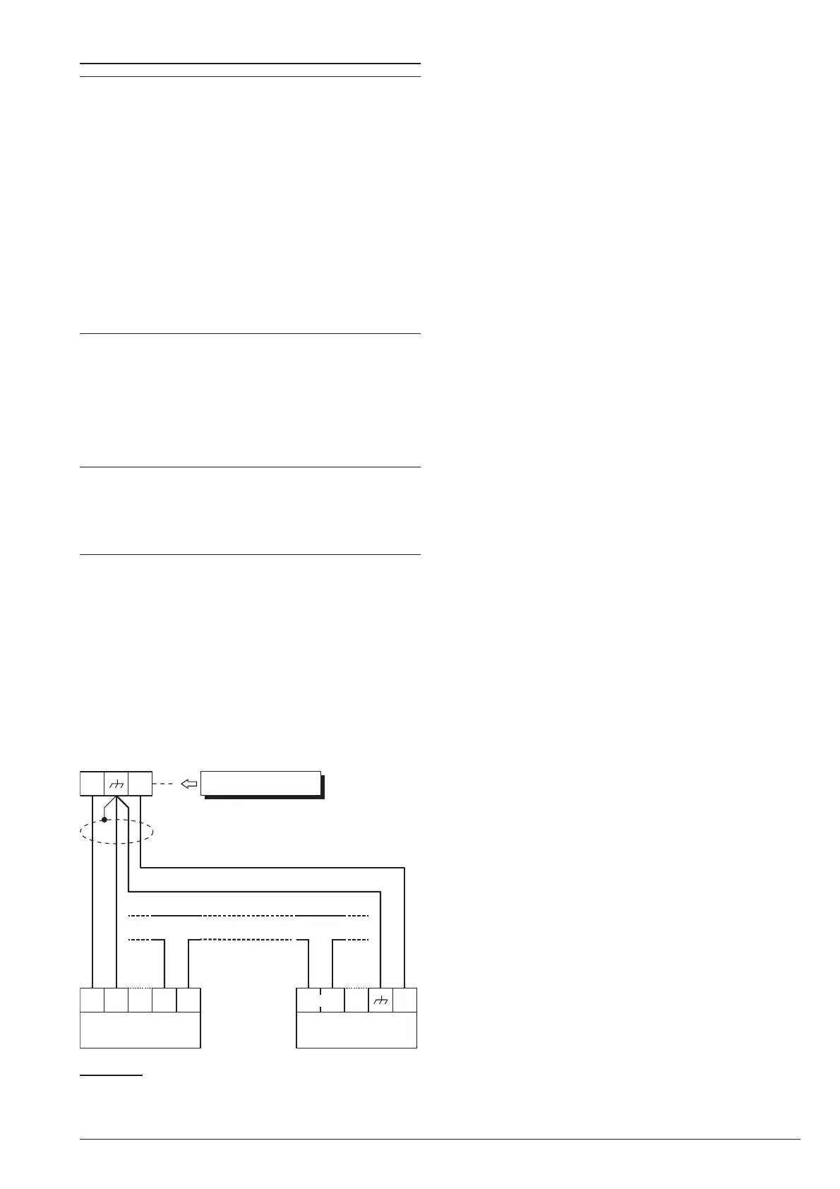
The wiring diagram in Figure 16 illustrates connection
of a Self-powered Siren and an Indoor Siren to Output
no. 1 on the Control Panel:
Ø
Output no. 1 on the Control Panel is programmed as
Normally Closed;
Ø
[+N] is the positive power and Input of the Self-pow
-
ered Siren. The Siren will activate when positive
(13.8 V) fails on the [+N] terminal;
Ø
[+B] is the positive power and Input of the Indoor Si
-
ren. The Siren will activate when positive (13.8 V) is
applied to the [+B] terminal;
Ø
[M] and [GND] are the negative power terminals of
the Self-powered Siren and Indoor Siren;
Ø [A.S.] and [AS1-AS2] are the Normally Closed Tam-
per contacts of the Self-powered Siren and Indoor Si-
ren.
To provide Tamper detection: connect the Signalling
device Tamper contact to the Control Panel Tamper
Line or to a 24h zone (refer to “Connecting Tamper
Contacts”).
32 Expandable Hybrid Control Panel
+A +N
self-powered
siren
A.
S.
AS1 AS2
GND
+B
indoor
siren
tamper line
+N
Control Panel
Figure 16 Connecting a Self-powered Siren and an In
-
door Siren to Control Panel Output no. 1.



 To Next Page