n
Supervised Output
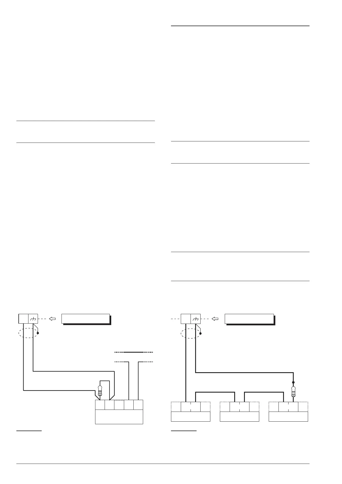
Output no. 1 can be set up as Supervised Output. This
type of output must be programmed as Normally
Closed (refer to “Attributes” under “Outputs” in the
“PROGRAMMING” section). The Control Panel can de
-
tect short-circuit and connection interrupt to terminals
+A of output with this attribute. The wiring diagram in
Figure 17 illustrates the connection of an Indoor Siren to
the Supervised Output using a 2.2 KW across terminals
+A and negative.
The 2.2 KW resistor (included in the package) have 3
red bands and a gold band. The last band (gold) indi
-
cates the tolerance, therefore, it may be a different
colour.
+
The 2.2 KW resistor must be connected to the last
device on the Output, otherwise it will have no ef
-
fect.
Short-circuit and connection interruption to terminal +A
of Supervised Output, will be signalled by:
Ø
Tamper on supervised output — relative to the
Output;
Ø
flashing on the a indicator on the Keypads.
Connecting Tamper Terminals
The Tamper contacts of the security system devices
can be connected to the SEOL Supervised 24h Tamper
Line.
The Tamper Line terminal is marked AS:
Ø
The Tamper Line will hold Standby status when con
-
nected to negative via a 10 KW resistor;
Ø
The Tamper Line will trigger an Alarm under all other
conditions.
Alarm on the Tamper Line will be signalled by:
Ø
a Tamper on Main unit event (by default, to comply
with EN50131, the Tamper on External Siren event
will occur);
Ø
flashing on the T indicator on Keypads.
+
The T indicator will flash until the cause of Alarm is
cleared (memory). The T indicator will stop flash
-
ing when the Control Panel resets.
The wiring diagram in Figure 18 illustrates the connec
-
tion of 3 Tamper contacts to the Control Panel Tamper
Line:
1. connect the device tamper contacts in series;
2. connect a 10 KW resistor in series to the last Tam-
per contact;
3. connect one end of the series to the [AS] terminal
and the other to the [M] terminal.
+
The 10 KW resistor must be connected to the last
device on the tamper line.
If the Tamper line is not used, connect a 10 KW re-
sistor across terminals [AS] and [M].
ABSOLUTA INSTALLING 33
tamper line
AS1 AS2
GND
+B
indoor
siren
+A
Control Panel
2.2 KW
Figure 17 Connecting an Indoor Siren to a Supervised
Output on the Control Panel.
A.
S.
AS
A.
S.
A.
S.
Control Panel
10 KW
Figure 18 Connecting 3 Tamper contacts to the Con
-
trol Panel Tamper Line — the [A.S.] terminals represent
the Normally Closed Tamper contacts of the device.
 Loading...