OPERON D 850 SURGICAL TABLE
PRINCIPLES OF OPERATIONS
Rev. 1 700000120
3-1
PRINCIPLES OF OPERATION
HYDRAULIC SYSTEM
WARNING
WARNING – POSSIBILITY OF
INJURY: The HYDRAULIC system
must be kept free of contamination.
Contamination can cause the
hydraulic system to fail, resulting in
personnel injury or equipment
damage.
CAUTION
CAUTION – The hydraulic system
on the OPERON D 850 surgical
table contains micro-hydraulic
valves, which are very sensitive to
contamination. Only a qualified,
trained service technician should
open the hydraulic system, and only
after all other repair procedures
have been tried. Always use clean
tools, and cover or wrap any loose
hydraulic lines with clean plastic
bags.
CAUTION
CAUTION — Use only BP Energol
HLP-HM 32 (or approved substitute
ARAL VITAM DE32) hydraulic fluid.
The use of other fluids could damage
the hydraulic system.
NOTE
NOTE – See (Ref) for the hydraulic
system schematics.
Hydraulic Power Unit
A hydraulic pump, driven by an electric motor,
is the primary source of hydraulic power. The
hydraulic pump has a relief valve set at 2175 PSI
(150 bar). The operating pressure is dependent
on the load on the pump and the flow required.
It can vary from 0 to 2175 PSI. Power unit is
mounted in the base.
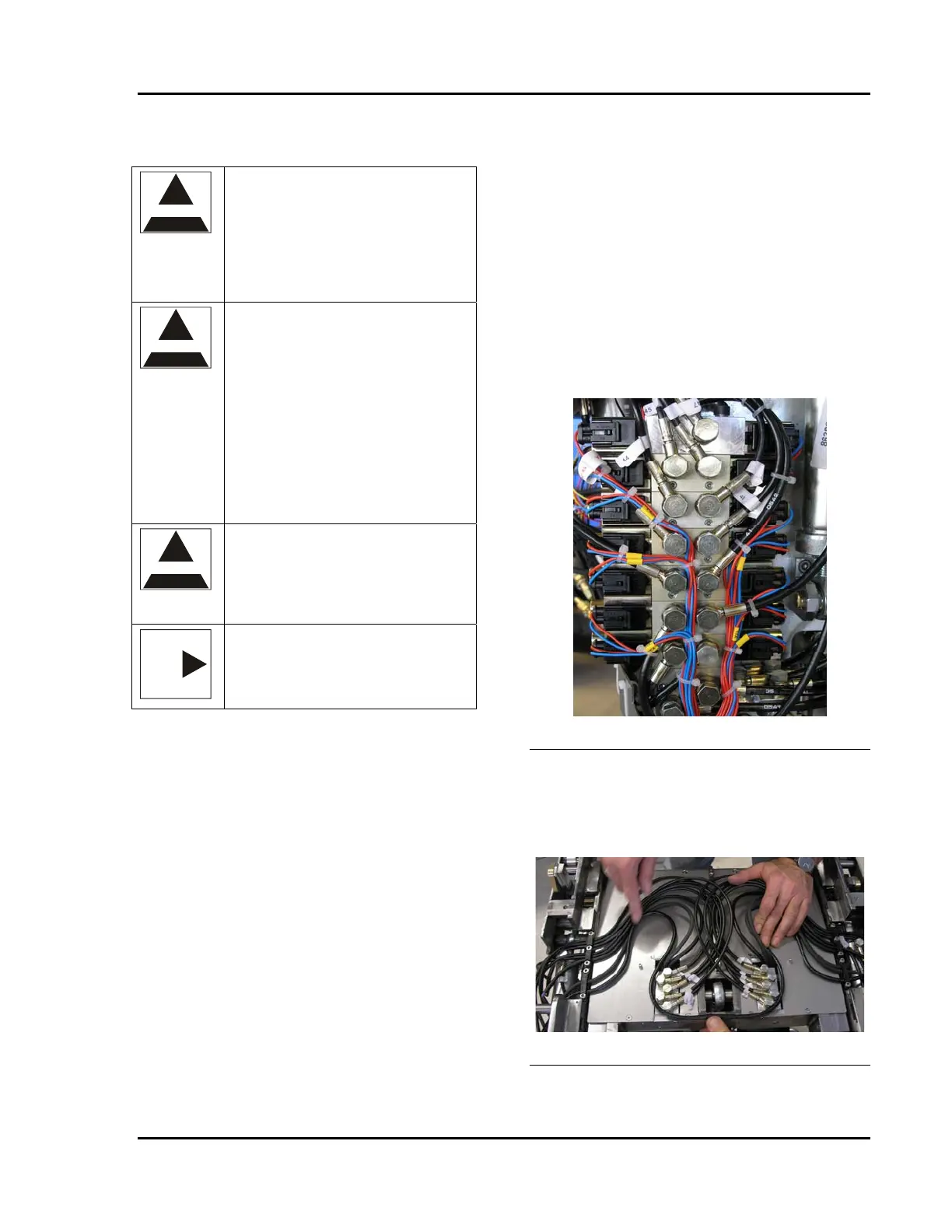
Hydraulic Manifolds
The table has 2 hydraulics manifolds and two
hydraulic distribution blocks. The manifolds
direct hydraulics fluid to valves and cylinders
that move various parts of the table. The
manifolds are made up of hydraulic valves that
are actuated by 24VDC solenoids. The solenoid
valves are field replaceable, but certain
individual hydraulic components that make up
the manifold are not field replaceable.
Each manifold has a 25 micron filter on the
input. There is an additional 60 micron filter
between the A and B sides of each valve (see
Table 4-2).
Column Manifold
A manifold on the main lift column provides
hydraulic fluid to the following cylinders
• Main lift cylinders (3)
• Trendelenburg cylinder
• Tilt cylinder
• Back cylinders (2 in parallel)
• Leg cylinders (2 in series)
• Kidney cylinders (2 in series)
Figure 3-1 Manifold Distribution Blocks
Two hydraulic distribution blocks, mounted
within the upper support frame, direct hydraulic
fluid from the column manifold to the Back,
Leg, and Kidney cylinders.
Figure 3-2 Distribution Blocks