OPERON D 850 SURGICAL TABLE
SERVICE
700000120 Rev. 1
5-7
Auxiliary Hand Pendant
The auxiliary hand pendant is a backup pendant
for use in case of a primary hand pendant
problem, or a power problem that disables the
CPU, main electric pump and/or the primary
hand pendant. It is identical to the primary hand
pendant and can be used to replace the primary
pendant.
The primary hand pendant sends commands to
the CPU via connection J24 on the CPU board.
The auxiliary hand pendant has all the functions
of the primary hand pendant with the exception
of AUTO DRIVE, HI/LO, SLIDES, FLEX,
REFLEX, CHAIR, UROLOGY, RETURN-TO-
LEVEL, OFF, and ON. The active functions on
the auxiliary pendant are back-lit.
An illustration of the auxiliary hand pendant
along with functions descriptions is provided in
the General Information of this manual.
The auxiliary hand pendant provides power to
the solenoids as long as the selected function
button is pressed and held. It does not activate
the hydraulic pump.
There are no field serviceable parts in the
auxiliary hand pendant. It must be replaced as a
complete assembly.
WIRING
The Appendix contains drawing 86799 which
identifies and locates all of the electrical wiring
and electronic components, as well as the
connections for each.
MECHANICAL SLIDE SYSTEM
The slide system uses a 24VDC motor to drive a
timing belt which, in turn, activates a slide screw
to slide the table top from head to foot. The DC
motor is reversible by controlling the current
direction, so no additional gearing is required to
achieve bi-directional motion. The motor is
secured in its mounting bracket by rubber
isolators that prevent vibration transfer to the
frame.
Components of the slide system were chosen for
high reliability and to minimize maintenance
requirements.
The motor provides high torque from a compact
design to fit in the space under the table top.
The motor assembles to the table top frame. The
motor, drive belt, the slide gear screw, nut and
its associated support bearing and mounting are
field replaceable.
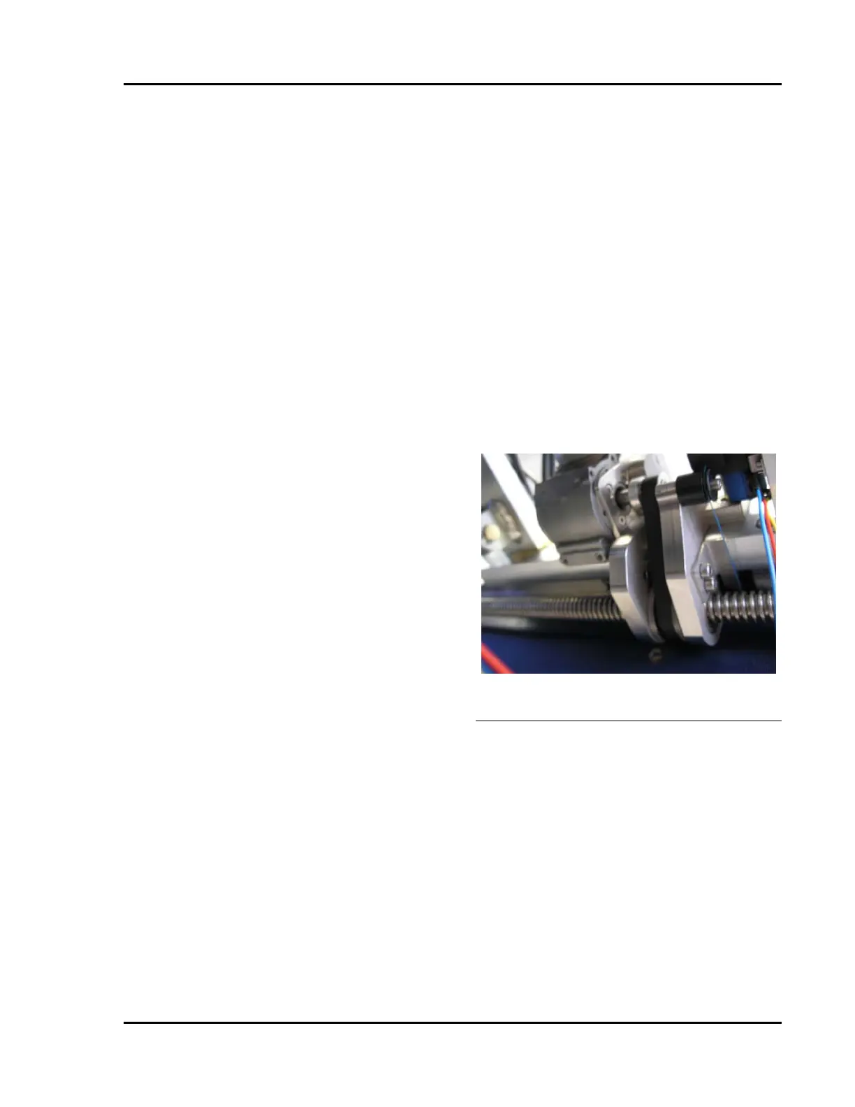
Figure 5-16 Slide Screw Drive Belt And
Potentiometer Cable Routing