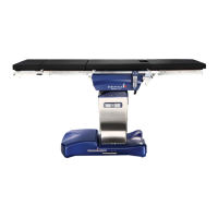
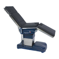
OPERON D 850 SURGICAL TABLE
PRINCIPLES OF OPERATION
Rev. 1 700000120
3-5
6. The variable flow control valve on the
return line can control the flow or
cylinder speed.
• A flow control screw on each valve
can be adjusted with a 2.5mm Alan
wrench.
• Turning the screw clockwise reduces
the flow. (See the drawing above for
the location of the flow control
screws.)
7. When power is removed from the
solenoid, the valve locks in the neutral
position. This prevents any cylinder
movement.
COLUMN HYDRAULICS
General Information
The drawing below shows a schematic of the
column cylinders.
All cylinders in the column are dual actuated,
which means that hydraulic pressure is required
to push the cylinder in both directions. The foot
locks, which are on the base, are single action
poppet valves: pressure is required only to move
the legs to the locked position.
There are 3 lift cylinders: One in the lower stage
and the other in the upper stage.
The lift cylinders are not field replaceable.
Although highly unlikely, a failure of one of
these cylinders will require that the table be
returned to the manufacturing facility for repair.
A loaner table may be shipped for the customer
to use while repairs are being made.
There is one Trendelenburg cylinder.
There is one Tilt Cylinder.
There are two hydraulic fluid distribution blocks
to connect many of the valves and cylinders.
The solenoid valves on the “A” side in the
schematic are on the left side of the hydraulic
manifold, and the solenoid valves on “B” side in
the schematic are on the right side of the
manifold.
All solenoid valve labels start with “Y”
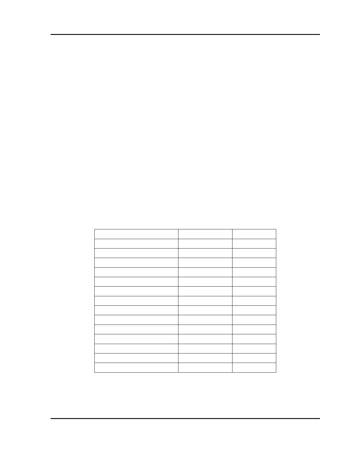
The column Solenoids and their functions are
listed below.
TABLE 3-2 COLUMN SOLENOIDS
Function Solenoid Valve Side
Tilt Up Y11 A
Tilt Down Y12 B
Trendelenburg Y21 A
Reverse Trendelenburg Y22 B
Height Up Y31 A
Height Down Y32 B
Kidney Up Y41 A
Kidney Down Y42 B
Back Up Y51 A
Back Down Y52 B
Leg Up Y61 A
Leg Down Y62 B
Leg Compensation Y63 A
Leg Compensation Y64 B