OPERON D 850 SURGICAL TABLE
PRINCIPLES OF OPERATION
Rev. 1 700000120
3-4
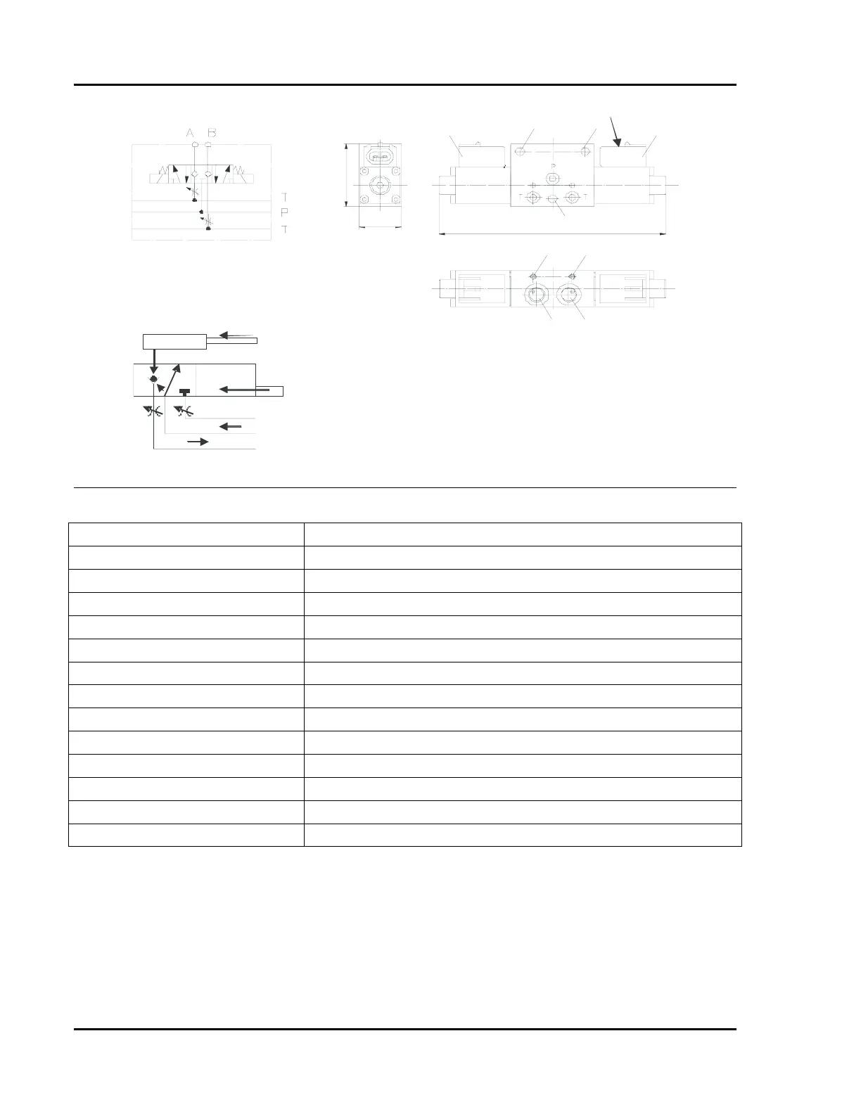
Neutral Position
Energized Position
Solenoid Coil
P Pressure Line
T Tank or Return Line
A, B Outputs Ports to Cylinders
1 Flow Control Adjustment Screws
2 Solenoid Coils Electrical Connection
3 Hydraulic Connection (M10)
4 Mounting Holes (0.21”/Ø 5.3mm)
Item Function
Ø
2
26
ca. 140
3
3
1
1
4
44
2
4
4
Figure 3-6 Manifold Valve
TABLE 3-1 MANIFOLD VALVE OPERATING SPECIFICATIONS
Parameter Range
Operating Pressure Up to 3626 PSI (250 bar) depending on flow rate
Flow Rate 61 in.
3
/min (3 dm
3
/min) maximum
Ambient Temperature -22 °F to +212 °F (-30 °C to +100 °C)
Pressure Medium Temperature
-7 °F to +176 °F (-20 °C to +80 °C)
Pressure Medium Hydraulic oil per DIN51524 and DIN51525
Viscosity Range 0.0006 in.
3
/s to 0.0195 in.
3
/s (10 mm
3
/s to 320 mm
3
/s)
Filtration 25 μm to 40 μm
Installed Position Any
Seal Material NB Rubber
Nominal Voltage 24 VDC (18 to 32 VDC)
Power Consumption 10 Watt (per solenoid)
Electrical Connection AMP Superseal Series 1.5 plug (double-pole)
Duty Cycle 100% ED
Manifold Valve Operation
The manifold valves operate as follows:
1. Hydraulic pressure is applied to the P
(pressure) fitting of a valve.
2. A solenoid coil (item 2) is energized by
an 18V -32V DC signal.
3. The coil forces the 3-position solenoid
spool to move. This is illustrated in the
section of the graphic labeled “energized
position”.
4. Fluid flows from the center pressure line
out to the cylinder.
5. A pilot pressure pushing on the check
valve opens the return path.