OPERON D 850 SURGICAL TABLE
OPERATING INSTRUCTIONS
Rev. 1 700000120
3-2
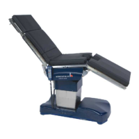
Floor Lock Manifold
One Manifold controls the floor lock system.
Located in the left foot section of the base, the
floor lock manifold directs fluid to the individual
cylinders lift the table off from its casters, thus
locking the table from horizontal movement.
The manifold contains no field replaceable parts.
It must be replaced as a complete unit.
Figure 3-3 Floor Lock Manifold
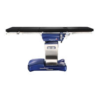
Figure 3-4 Location of Floor Lock
Manifold In Base
FLOOR LOCK SYSTEM
The floor lock system uses 4 hydraulic cylinders
in parallel as shown.
The floor lock system can compensate for
uneven floors up to 0.25” (6mm). This is
accomplished by using 2 pressure switches to
control the fluid flow to the cylinders.
The sequence of events when locking and
unlocking the feet is as follows (the table base
ON/OFF switch must be ON):
1. Power is applied to pressure switch P2 to
tell the controller the status of the feet.
2. The Lock button on the hand pendant is
pressed, initiating the pump and
pressurizing the manifold.
3. Power is applied to solenoid Y71 and
pressure switch P1
4. Fluid flows to cylinders 1 and 2 via the
one way check valve in solenoid Y73.
5. Cylinders 1 and 2 move to full stroke.
When they reach full stroke, the pressure
continues to build until it reaches 1740
PSI (120 bar).
6. At 1740 PSI (120 bar), pressure switch P1
closes.
7. Solenoids Y74 and Y75 energize and
allow fluid to flow to feet 3 and 4 via the
extension board. LEDs on the extension
board will turn on and off to indicate
movement of the locks.
8. When valves Y74 and Y75 are open, the
pressure is the same at feet 3 and 4. If the
floor is uneven, the fluid will flow to the
foot with the least resistance, which on an
uneven floor, is the one that must travel
the most distance.
9. When both feet hit the floor, the pressure
increases.
10. Pressure switch P2 closes when the
pressure reaches 580 PSI (40 bar).
11. When P2 closes, a signal is sent to the
controller that the feet are locked,
illuminating the lock LED on the
pendant, and de-energizing the pump and
the power to P1, Y74, and Y75.
12. When Unlock is pressed, Y72 is
energized, allowing pump pressure to
open the pilot valves. Y73 is energized to
allow fluid to flow from feet 1 and 2, and
fluid flows freely from Y74 and Y75 via
their check valves. Springs in each foot
push the fluid out, allowing the feet to
retract.