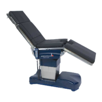
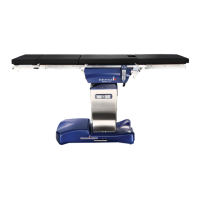
OPERON D 850 SURGICAL TABLE
SERVICE
700000120 Rev. 1
5-1
SERVICE
HYDRAULIC FLUID
The OPERON D 850 Surgical Table hydraulic
system uses BP Energol HLP-HM 32 (or ARAL
VITAM DE 32) hydraulic fluid (see Drawing
306762 in Section 8). This hydraulic fluid is
available world wide, but can also be purchased
from BERCHTOLD.
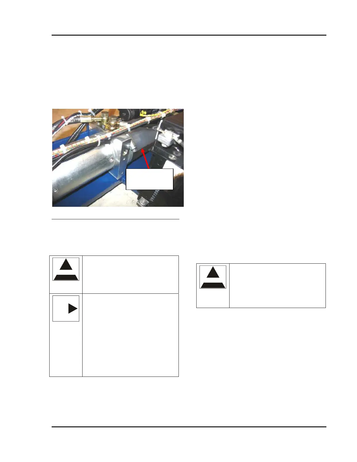
Figure 5-1 D 850 Reservoir
This is the reservoir fluid height with the table
raised to its maximum height and with the table
sections level
ELECTRONIC CONTROL SYSTEM
WARNING
WARNING – When servicing the
table, turn power off or remove the
appropriate fuses to prevent personal
injury. If power is required, use care
to avoid contact with live parts.
NOTE
NOTE – The table can be factory
configured for 230 VAC operation
based on customer order
requirements. The modifications
involve only components associated
with the AC mains supply. The
information below describes only the
115 VAC components. Refer to the
schematic diagrams in Section 5 and
the parts listing in Section 8 for
identification of the 230 VAC
components.
The electrical system is made up of 7 parts:
1. CPU & Control wiring
2. Position Sensors and Switches
3. Power Supply System
4. Power Input System
5. Controls (Main and Auxiliary Pendants)
6. Slide Motor
7. Drive Motor (optional)
CPU
The Central Processing Unit (CPU) is the brains
of the table. It contains the software and
controls the operation of the solenoids and
power unit based on inputs from the operator
(via the pendant) and signals from the table (via
the positioning sensors and switches).
A second controller serves as a back up for the
primary CPU allowing basic function control of
the valves. In the event of a failure of the
primary CPU, the auxiliary pendant can be used
with the foot pump.
The CPU is located on the column beneath the
column covers. The CPU contains no field
serviceable parts. It must be replaced as a
complete assembly.
See drawing 86799 for wiring connections and
electrical component locations
CAUTION
CAUTION – Do not mix hydraulic
fluid types. Other hydraulic fluids
can be incompatible with the seals in
the OPERON D 850 table and can
cause equipment failure or reduce the
service life.
Communication Interface (RS232) Board
The connector board is located on the top of the
bellows on the left side of the table. This board
connects the CPU to the RS-232 PC interface
Position Sensors and Switches
The position sensors provide the CPU with
information about the position of the table for
use in return-to-level, chair, and flex settings,
and in software control limits. Drawing 86799
in the appendix shows the location of all sensors.
58 mm from
the base