3.2 Installation of the Measuring Device
26
Procedure:
A) Installation of Measuring Frame
See also the Mechanical Drawings on page 133
□ The measuring frame has to be split up into two parts,
the foot with the shielding (Figure 14) and the top part,
consisting of the two verticals and the crossbeam
Figure 16: Bottom plate of measuring frame foot
□ Base and bore holes (Figure 16) for installation of the
measuring frame foot at a suitable site according to the
dimensions below the conveyor belt and in a suitable
height.
□ Insert measuring frame foot and fix it.
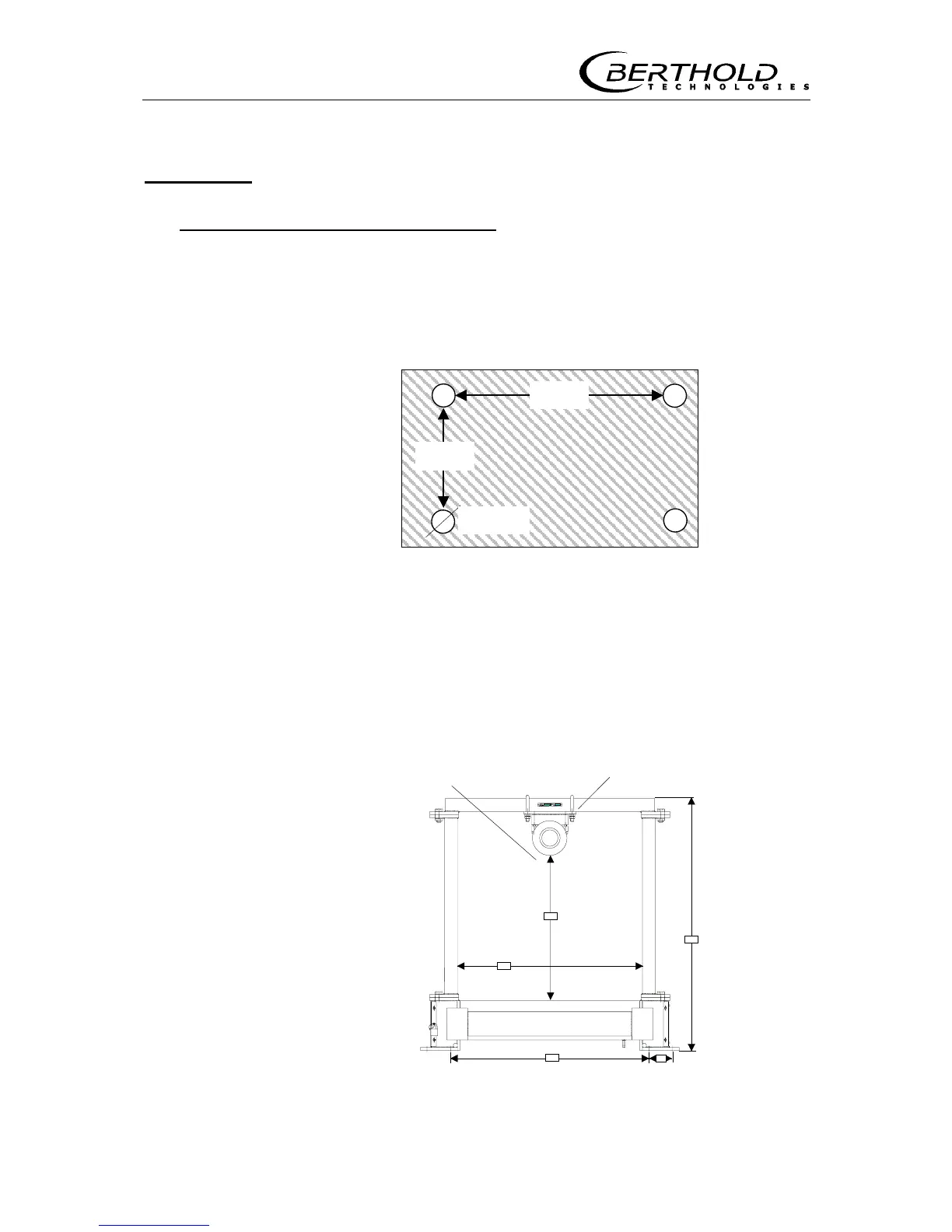
□ Screw top part of measuring frame onto foot.
Detector Detector holder
a
c
b
d
e
Figure 17: Measuring frame
300m
90mm