LB 983 NightSHADE Operating Manual System Description
75
5.3 Acquisition Chamber
5.3.1 Light-tight Door with Door Button
To close the acquisition chamber light-tight, the door frame is provided with an elastic sealing
and a handle which, when turned by 180°, will pull the door into the frame and squeeze it
against the sealing. An inductive sensor indicates if the door is closed correctly.
Always make sure that the door is properly closed. If the door is not closed and you try to take
an image, you will be alerted by the program.
Images can be taken even while the door is open. The camera is insensitive to daylight, i.e. the
camera will not be destroyed by overexposure.
5.3.2 Illumination of the Acquisition Chamber (Dark Box)
Four LED's installed on the walls of the dark box ensure constant illumination of the acquisition
chamber. However, the illumination depends on the camera setting and with very low camera
position it can be affected adversely. If necessary, an additional light source has to be installed
(power is supplied via the outlet strip in the acquisition chamber).
The illumination of the acquisition chamber is automatically controlled by the software.
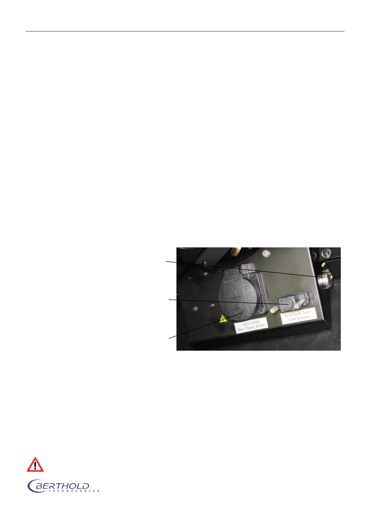
5.3.3 Connector Field
The connector field is located in the right rear corner of the acquisition chamber; it includes the
following ports:
The mains socket is controlled through the software (see chapter 4.2.4) To prevent exposure to danger-
ous UV light when using e.g. a UV transilluminator the socket will switch off while the door is open.
Max. power outlet is 200VA.
The CAN socket controls external system options such as the turn table (see chapter 10.1.2) or the tem-
perature controlled measurement table (see chapter 10.1.4).
When no external equipment is connected the dummy plug (terminator) must be connected to this socket
to ensure a proper termination of the internal bus.
The two round connectors at both sides of the connection box are the power supply and control outlet for
the optional LED panels (see chapter10.1.1).
Connect the LED panels only while the instrument is powered off to prevent electrical damage of
the LED panel.
CAN socket: System connectors to
control instrument op-
tions (e.g. turn table)
Mains socket: Mains socket enabled
via software
Round sockets: Control connector for
LED panels (left and
right)