540
PROPULSION SYSTEMS
Studio ti 03312 540-04usa
134
8
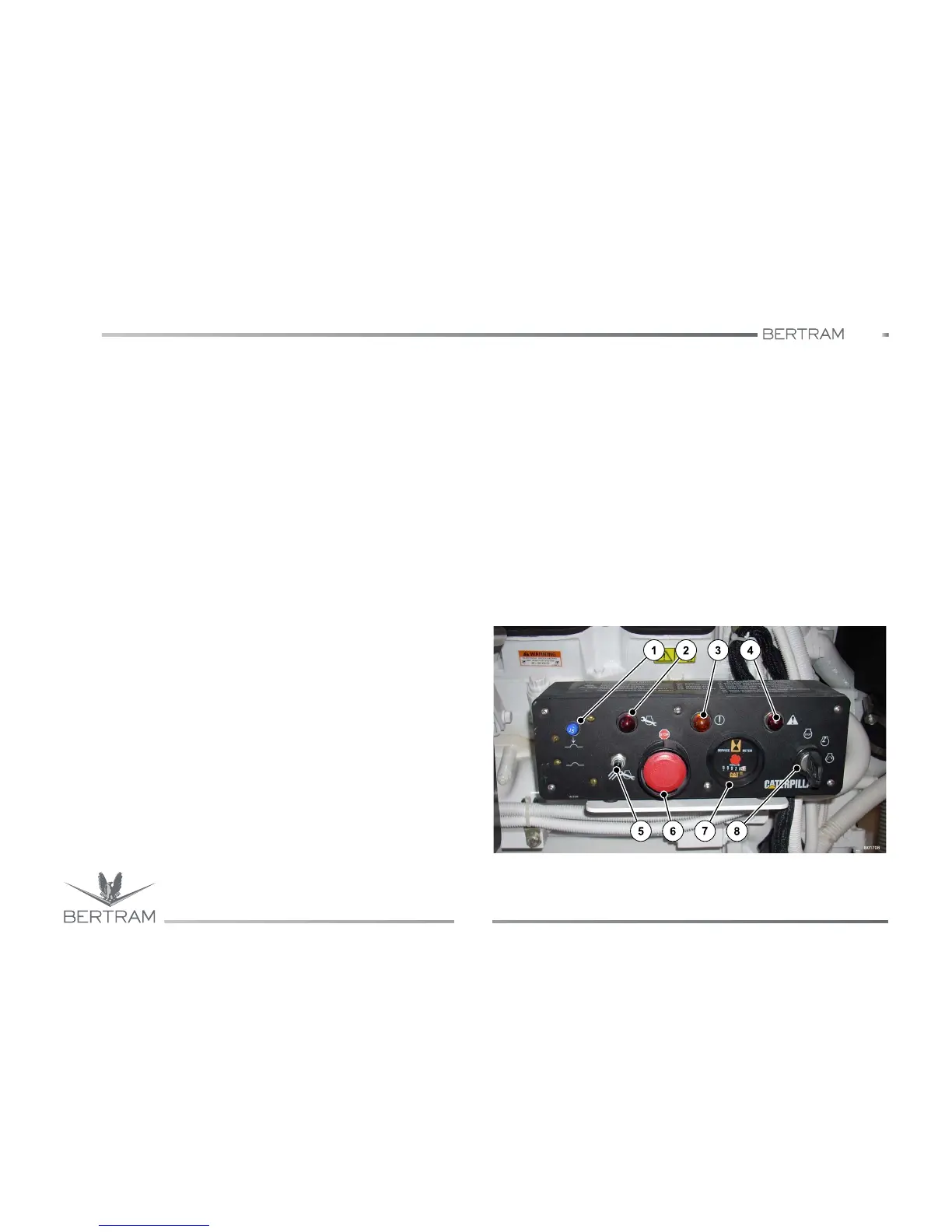
Control panel
1. Circuit switch reset
Three resets for the circuit switch are available on the control panel:
two automatic resets (15 A) and a manual one (15 A). Check for
complete lack of electric power supply of the engine.
2. Maintenance LED
This LED blinks when programmed maintenance has to be carried
out.
3. Diagnostics LED
This LED blinks when a diagnostic code has been generated by the
ECM. The active diagnostic code will blink.
4. Signal lamp
This LED blinks because of critical situation, for instance oil pressure
insufficient or temperature of coolant is too high.
5. Maintenance clearing button
When the engine has been serviced, press this button to switch off
the maintenance lamp.
6. Emergency stop button
The OUT position is for normal engine operation. Press this button to
stop the engine for an emergency. The start button does not actuate
the circuit breaker of the starter while the emergency button is
pressed. Reset this button before starting the engine. Turn the button
clockwise to release it and allow the start.
7. Hours counter
The hours counter checks the engine service hours. It actuates only
with running engine.
8. Starter switch
The starter switch has three detents: OFF, RUN & START. When
turning the switch clockwise to RUN, the LEDs flash for five seconds
during the system test, then switch off. In RUN position, the ECM and
the electronic systems are powered.
When you turn the switch to START, the circuit breaker of the starter
actuates. The electric starter switches on. The starter carries on
turning while the starter switch stays in START position. The starter
switch is spring loaded, so as to return to RUN when the switch is
released. The engine can be shut off by positioning the starter switch
to OFF. This kind of disconnection cuts off the power to the ECM.