540
10
ELECTRIC SYSTEM
Studio ti 03312 540-04usa
237
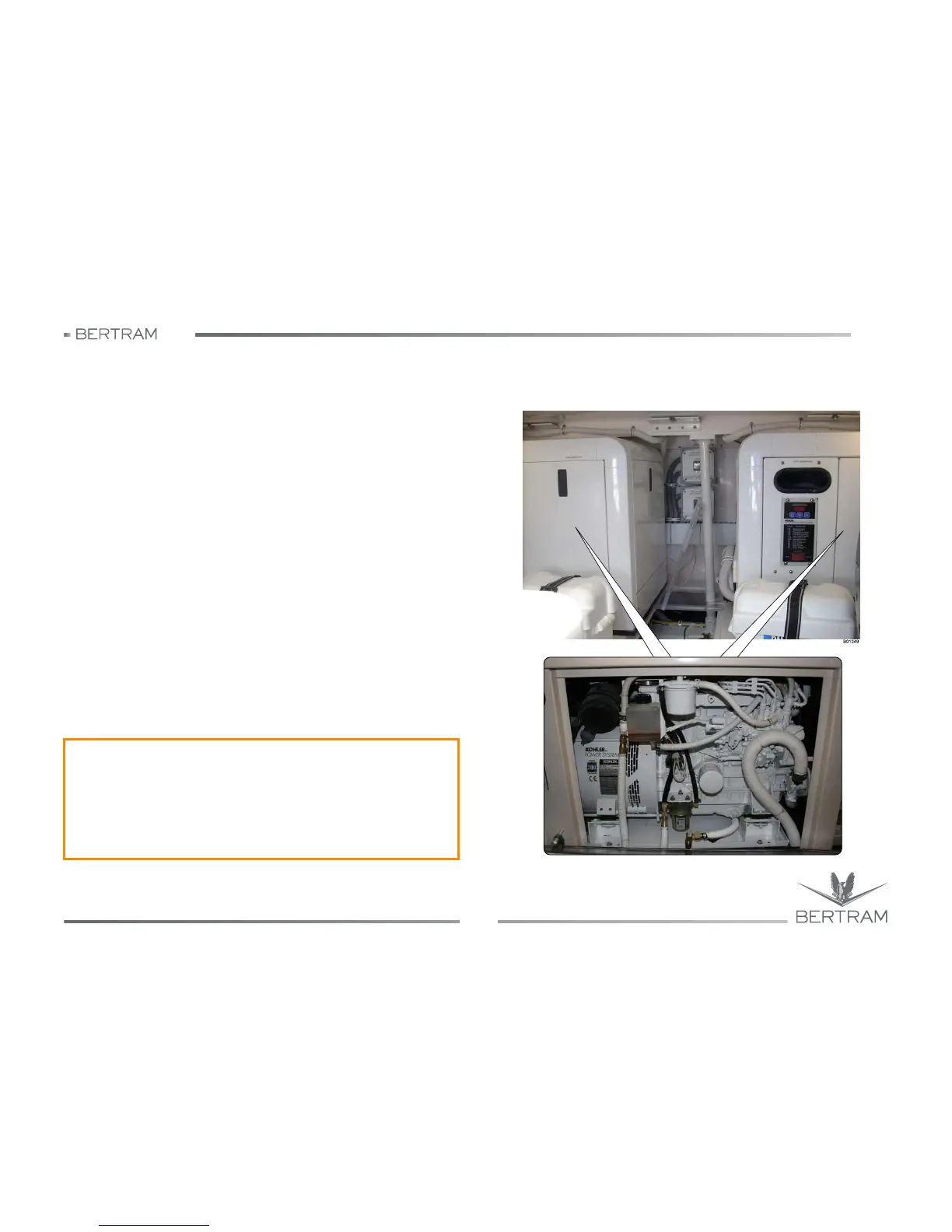
10.8 POWER GENERATOR
10.8.1 Operation
On board of your BERTRAM 540 yacht are installed two KOHLER
generators, located in the generators’ room. On the fuel tank, you can
easily locate the power generator supply, which can be cut-off by means
of two delivery valves, on which you can handle to cut off the fuel lines in
case of emergency and to shut off the generators. The connections going
from the generators to the tank are for fuel flow-back. The exhaust gases,
instead of being discharged directly overboard, are conveyed by means
of a silencer, installed on each generator and located in the helm gear
compartment and then discharged overboard. These silencers, through
the injection of water in the exhaust tubes, allows to cool down the fumes
and at the same time, to reduce the noise produced by he water outflow.
The intake seacocks of the cooling circuit are installed on the hull with the
sea water filters fastened to a surface near to intake seacock valves.
Clean the intake seacock filters according to the frequency of the system
use and to the condition of the sucked waters. Before cleaning the
strainers, remember to close the hull valves, then proceed with
maintenance. When the cleaning is complete, REOPEN the valves
feeding the cooling circuit. The generator may be operated either by the
remote electric panel or at the generator through the control panel located
on the unit in the engineroom. The generator is also equipped with a
battery disconnect switch.
For detailed information about generators operation and maintenance
procedures, see the manufacturer manual.
KOHLER 22 EFOZD (230 V - 50 Hz) and KOHLER 13 EFOZD (230 V - 50 Hz)
j
WARNING
It is highly recommended to empty the generator muffler after several
(three) failed attempts to start the generator.
If this precaution is not observed, water reaches the generator through
the exhaust manifold. The exhaust control panel is located at the
bottom of the generator muffler.