CB (E6.1) 07/2017 Page 16/145
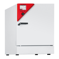
2. Chamber description
The CO
2
incubators CB are equipped with a multifunctional microprocessor display controller for
temperature, CO
2
, and O
2
(chamber with O
2
control) levels and a digital display accurate to one-tenth of a
degree resp. 0.1 vol.-%
The inner chamber, the pre-heating chamber and the inside of the doors are all made of stainless steel
V2A (German material no. 1.4301, US equivalent AISI 304). The inner surfaces are smooth and therefore
easy to clean. The inner chamber is deep-drawn from one piece, polished (suitable for pharmaceutical
applications) and has no welds or inaccessible corners. The hinges and the seal of the inner glass door
are glued from the outside to aid cleaning of the inner chamber. When operating the chamber at high
temperatures (sterilization), the impact of the oxygen in the air may cause discoloration of the metallic
surfaces (yellowish-brown or blue) by natural oxidation processes. These colorations are harmless and
will in no way impair the function or quality of the chamber.
The perforated shelves are also made of stainless steel. You can insert a maximum of 3 (CB 60), 6 (CB
160), resp. 8 (CB 220) shelves.
The housing is RAL 7035 powder-coated. All corners and edges are also completely coated.
The chamber’s heating system permits hot-air auto-sterilization at a setpoint of 187.5 °C / 369.5°F. Thus,
a temperature of 180 °C / 356°F is maintained for at least 30 minutes on all internal surfaces, resulting in
sterilization of the entire inner chamber. Therefore, this procedure meets all international guidelines
regarding hot air sterilization, e.g. AAMI ST63, DIN 58947, European Pharmacopoeia.
Thanks to the standard safety device (class 3.1 according to DIN 12880), the set temperature is
maintained in case of failure.
The gas enters the chamber via a fine filter (aseptic filter) with a high filtration efficiency that also filters
the smallest particles.
A highly precise, drift-free CO
2
infrared measuring system in combination with the permanent mixture of
CO
2
gas through a special proprietary gas mixing head developed by BINDER allows precise and
constant CO
2
concentrations for long periods. This creates optimum growth conditions for cultures.
The CO
2
incubator is also available with O
2
control in addition to CO
2
control. There are two different
control ranges:
• Regular equipment: Hypoxic control range 0.2 to 20 vol. % O
2
. Only N
2
can be connected to reduce
O
2
concentration; it is not possible to connect O
2
gas bottles to increase O
2
concentration. Control in
the low O
2
range is very precise, in particular in the range below 1 vol. % O
2
.
• Alternative control range 10 to 95 vol. % O
2
(option no. 8012-1106). Although the high control range is
intended in particular for hyperoxic applications (> 21 vol. % O
2
), it is also suitable for slightly hypoxic
applications between 10 and 20 vol. % O
2
.
CO
2
and O
2
sensors
Fast reaction times, maximum accuracy and selectivity characterize the CO
2
measuring procedure of
the CB incubator series. The accuracy of the CO
2
measuring system is based on a double-beam
infrared measuring cell with NDIR (non-dispersive infrared) sensor, which continuously regulates to a
reference value. Therefore, disturbance variables and aging phenomena in the measuring system are
almost completely eliminated, so that this measuring system, in contrast to other measuring
procedures, remains practically drift-free between calibrations and is entirely selective for CO
2
. The
sensor is built into the chamber and can be sterilized.
The O
2
sensor is a semiconductor gas sensor with ZrO
2
ceramic.
The accuracy of the indicated values of CO
2
and O
2
(chamber with O
2
control) depends on the
ambient air pressure (approx. 0.08 vol.-% per 10 mbar / 0.15 psi). To compensate for this effect in the
CO
2
measurement, the controller measures the ambient air pressure and automatically includes it in
the calculation.
The chambers are equipped with an Ethernet interface for computer communication, e.g. with the
communication software APT-COM™ 3 DataControlSystem (option, chap. 15.1). For further options, see
chap. 22.5.