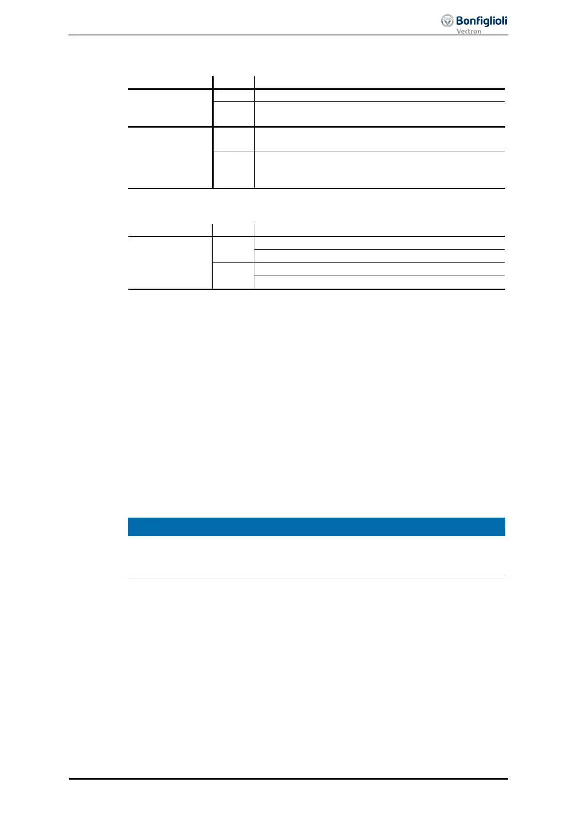
limit switch mode
Bit 4
Do not start or stop movement.
Start (or resume) movement from limit switch to travel
range.
Bit 8
Execute command from bit 4 “Move away from limit
switch”.
Stop axis with ramp of current motion block (The fre-
quency inverter remains enabled in “Operation enabled”
Bit 10
0
Limit switch still active
1
In mode -2 “Move away from limit switch”, the drive is cleared from a triggered hard-
ware limit switch or software limit switch. The direction of rotation depends on the
active limit switch: If the positive limit switch is active, the drive moves to negative
direction and vice versa.
“Move away from limit switch” mode is started in status “Operation enabled” by con-
trol word bit 4 “Move away from limit switch”. The drive is accelerated with the ramp
from parameter Acceleration 1134 to the speed set in parameter Creep speed 1133
Once the active
limit switch has been cleared, the drive is stopped. Once speed 0 has
been reached, status word bit 10 “Target reached” will be set.
When both directions of rotation are blocked, e.g. due to simultaneous triggering of
positive and negative limit switch, error message “F1449 Both directions locked”. In
this case, the function “Move away from limit switch” cannot be used.
In the clearing phase of a hardware limit switch, the hysteresis defined in parameter
Hysteresis 1149 will be active. After detection of the limit switch edge, the axis will
be moved on, at least by the defined hysteresis distance.
Setting
Halt
to
“
1” will stop the started clearing operation. The axis will be stopped.
Sta
tus bit “Target reached” is set to “1” when the speed reaches value 0. The drive
remains in “Operation enabled” status. By resetting
Halt
to “0”, the interrupted clear-
ing operation will be continued, and “Target reached” will be reset to “0”.
10/13
ACU
Modbus/TCP 107