EasyManua.ls Logo

BONFIGLIOLI Active Cube User Manual

BONFIGLIOLI Active Cube
134 pages
To Next Page IconTo Next Page
To Previous Page IconTo Previous Page
Page #128 background image
14.3 Warning messages
The different control methods and the hardware of the frequency inverter include functions for con-
tinuous monitoring of the application. In addition to the messages documented in the frequency in-
verter user manual, further warning messages are activated by the Field Bus module. The bit-coded
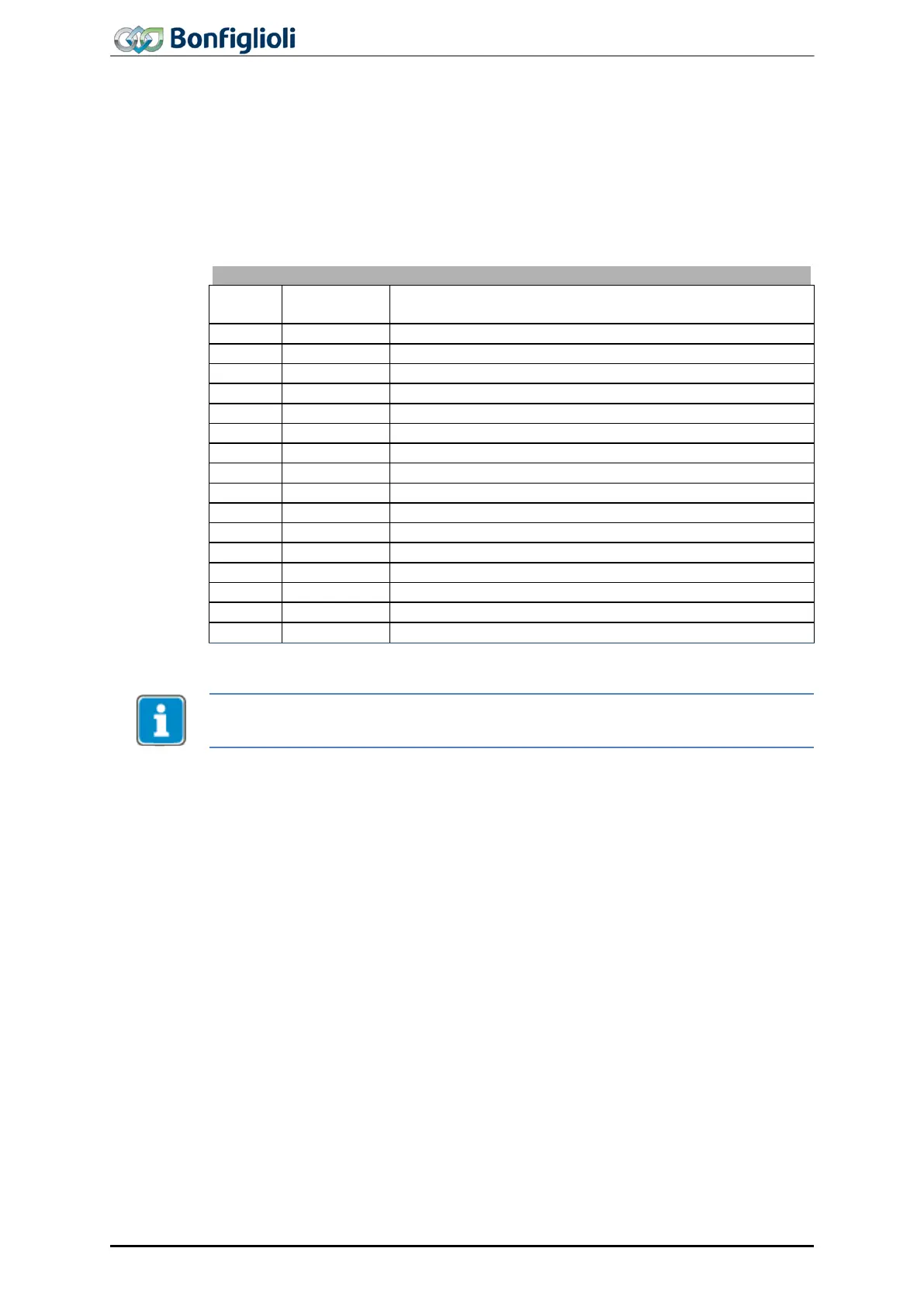
warning reports are issued via parameter
Warnings 270 according to the following pattern: Parame-
ter
Warnings 270 is provided for read-out via a PLC, Parameter Warnings 269 provides the infor-
mation, including a brief description in VPlus and the control panel.
Warning messages
Bit no.
Warning
code
Description
0
0x0001
Warning Ixt
1
0x0002
Warning short-time Ixt
2
0x0004
Warning long-time Ixt
3
0x0008
Warning heat sink temperature Tk
4
0x0010
Warning inside temperature Ti
5
0x0020
Warning Limit
6
0x0040
Warning Init
7
0x0080
Motor temperature warning
8
0x0100
Warning mains failure
9
0x0200
Warning motor circuit breaker
10
0x0400
Warning Fmax
11
0x0800
Warning analog input MFI1A
12
0x1000
Warning analog input A2
13
0x2000
Warning System Bus
14
0x4000
Warning Udc
15
0x8000
Warning Application warning status 367
The meanings of the individual warnings are described in detail in the frequency in-
verter Operating Instructions.
126
ACU
Modbus/TCP 10/13

Table of Contents

Other manuals for BONFIGLIOLI Active Cube

Question and Answer IconNeed help?

Do you have a question about the BONFIGLIOLI Active Cube and is the answer not in the manual?

BONFIGLIOLI Active Cube Specifications

General IconGeneral
BrandBONFIGLIOLI
ModelActive Cube
CategoryInverter
LanguageEnglish

Summary

GENERAL SAFETY INSTRUCTIONS AND INFORMATION ON USE

Designated use

Specifies the inverter's intended design and use in industrial plants and machines.

Residual risks

Details hazards that cannot be eliminated despite safety-compliant design, including electrical, thermal risks.

Safe operation

Outlines safety measures during operation, including cover checks and avoiding unauthorized modifications.

Maintenance and service/troubleshooting

Describes procedures for maintenance, inspections, and repairs, emphasizing qualified personnel.

First commissioning

Assembly/disassembly of communication module

Assembly

Details the process for installing the CM-Modbus/TCP communication module into the frequency inverter.

Modbus/TCP interface

Communication modules

Describes the CM-Modbus/TCP and CM-Modbus/TCP-2P modules and their RJ45 ports.

Protocol

Supported function codes

Lists Modbus function codes used for reading and writing 16-bit and 32-bit values.

PARAMETER ACCESS

EXAMPLE MESSAGES MODBUS/TCP

16-bit access

Provides examples of Modbus/TCP telegrams for reading and writing 16-bit parameters.

32-bit access

Demonstrates Modbus/TCP telegram examples for reading and writing 32-bit parameters.

MOTION CONTROL INTERFACE (MCI) / MOTION CONTROL OVERRIDE (MCO)

Functions of Motion Control Interface (MCI)

Covers reference systems, modes of operation, and parameters for MCI.

CONTROL OF FREQUENCY INVERTER

Control via contacts/remote contacts

Details control methods using digital inputs and remote contacts, including status word bits.

Control via state machine

Explains control via the state machine using the control word and status word.

Motion control configurations

Explains how motion control configurations use control and status word bits for various modes.

Parameter List

Parameters (Menu “Para”)

Lists all available parameters, their ranges, and related chapters.

APPENDIX

Error messages

Explains error codes, their groups, and meanings for motion control and Ethernet communication.

Related product manuals