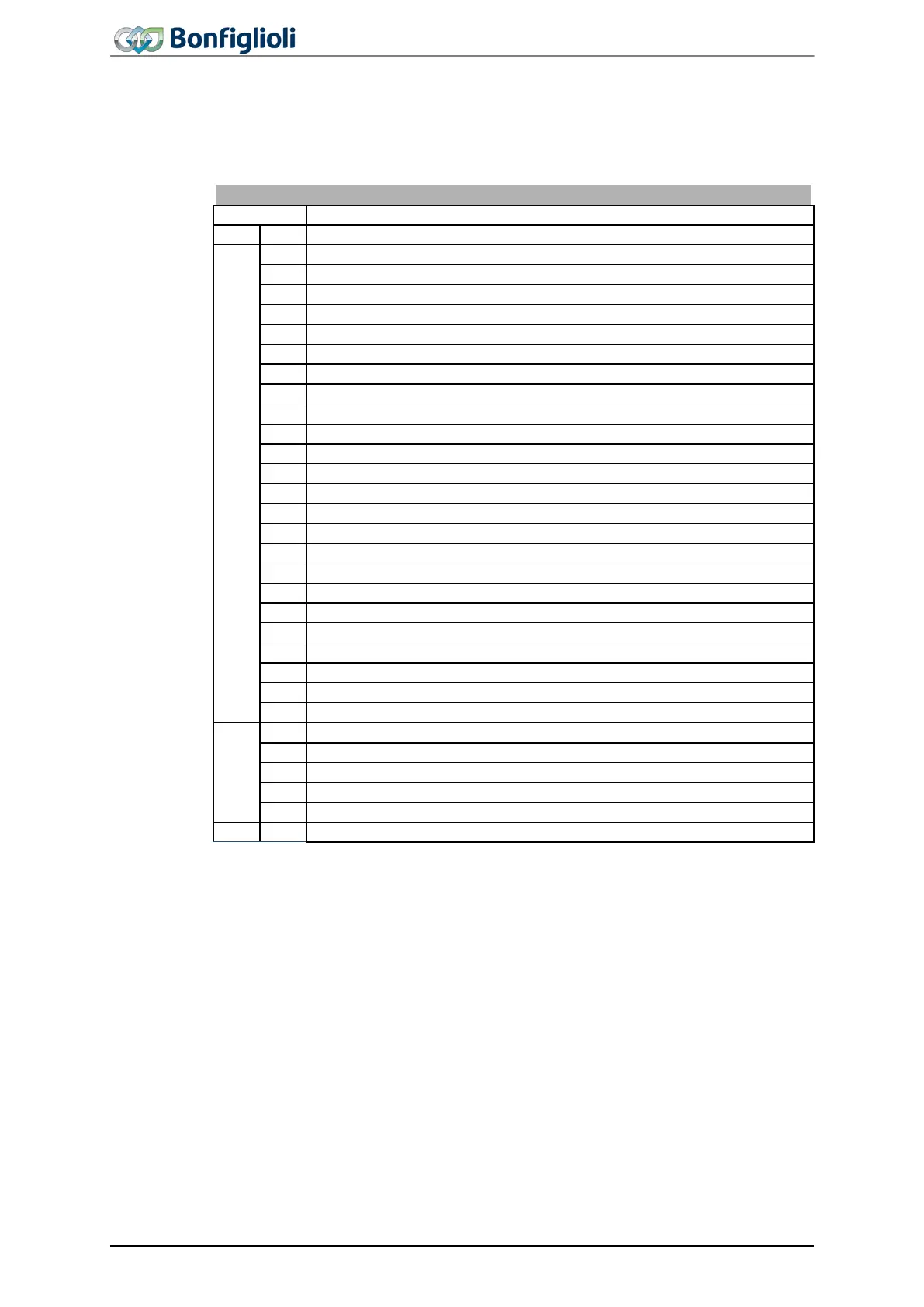
14.5 Error messages
The error code stored following a fault comprises the error group FXX (high-byte,
hexadecimal) and the code YY (low-byte, hexadecimal).
Control deviation position controller
Pos. SW limit sw. < Neg. SW limit sw.
Pos. and Neg. HW-Lim Switch Simultaneously
Limit Switch Incorrect Wired
Switch: Pos. Dir. Blocked
Switch: Neg. Dir. Blocked
System bus-Synchronization not activated
Pos. HW Limit Sw.: Non-permissible signal source
Pos. HW Limit Sw.: Input deactivated by PWM /FF input
Pos. HW Limit Sw.: Input deactivated of index controller
Pos. HW Limit Sw.: wrong mode for MFI1
Pos. HW Limit Sw.: Input deactivated by encoder 1
Pos. HW Limit Sw.: Input deactivated by encoder 2
Pos. HW Limit Sw.: wrong mode for EM-S1IOD
Neg. HW Limit Sw.: Non-permissible signal source
Neg. HW Limit Sw.: Input deactivated by PWM /FF input
Neg. HW Limit Sw.: Input deactivated of index controller
Neg. HW Limit Sw.: wrong mode for MFI1
Neg. HW Limit Sw.: Input deactivated by encoder 1
Neg. HW Limit Sw.: Input deactivated by encoder 2
Neg. HW Limit Sw.: wrong mode for EM-S1IOD
User-Defined Error in Motion Block xx (1 £ xx £ 32)
Homing Encoder-Mode w.o. Z-Impulse
No Touch Probe Signal Detected
Communication loss to PLC
The current error can be read via parameter Current error 260.
Parameter Current error 259 indicates the current error as plain text
panel and the VPlus PC control software.
In addition to the error messages mentioned, there are other error messages speci-
fied in the Operating Instructions. The errors of the Motion Control Interface (F14xx,
F15xx) are described in detail in the “Positioning” application manual.
128
ACU
Modbus/TCP 10/13