Starting of Master/Slave Position Correction in Slave drive
To start the Master/Slave Position correction at first Bit 4 and then Bit 5 have to be set
in the Control word. Bit 5 is only allowed to be set when Bit 10 In Gear is shown in the
Status word.
By setting Bit 5 in the Control word the Slave drive is started to position to the Master
position + Offset.
The acceleration is done with Parameter
Acceleration 1134
. The used velocity can be
set up via Parameter Fast Speed
1132.
As long as the Master/Slave Position correction is executed, Bit 12 is deactivated in the
Status word. When the Master/Slave Position correction is finished successfully Bit
During the Correction sequence the Status
word bit 8 “Master/Slave Position corre
c-
tion” is set to “Low”. As soon as the Master/Slave Position correction is finished or
cancelled, the Bit is set to “High”. After first switch
-
on (or after a device reset) the
“Phasing Done” bit is also “Low”.
Since Bit 8 is also used for Phasing, always the last started function is signaled by this
bit.
The Offset for the M/S Synchronization can be set via M/S Synchronization offset
1284.
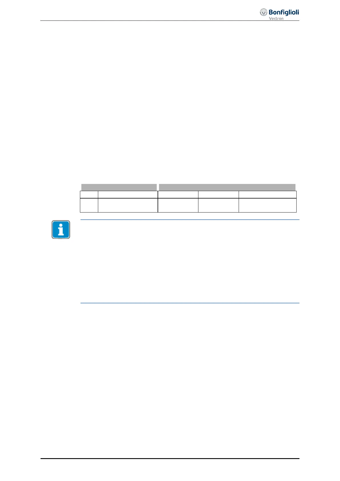
1284
M/S Synchronization
offset
2147483647 u
0 u
The function can be used in most of all applications without any limitations. In appli-
cations with very long travelling distances the following must be checked:
• The position difference to be compensated must not be greater than 2
15
-1
motor revolutions.
• The position difference to be compensated must not be greater than 2
31
-1
user units.
Depending on the used reference system it can va
ry, which limit is decisive. Always
the smaller limit must be complied with.
A motor with a reference speed of 6000 rpm would have to travel for around 5.5
minutes into one direction to exceed this limit.
10/13
ACU
Modbus/TCP 117