Depending on the selected mode of operation, various objects and parameters are
used. The various objects and parameters must be set specifically for the different
modes of operation.
Use of “Deceleration” and “Quick Stop” depends on the modes of operation, control
commands and behavior in the case of communication errors (see
Bus Error Beha
388).
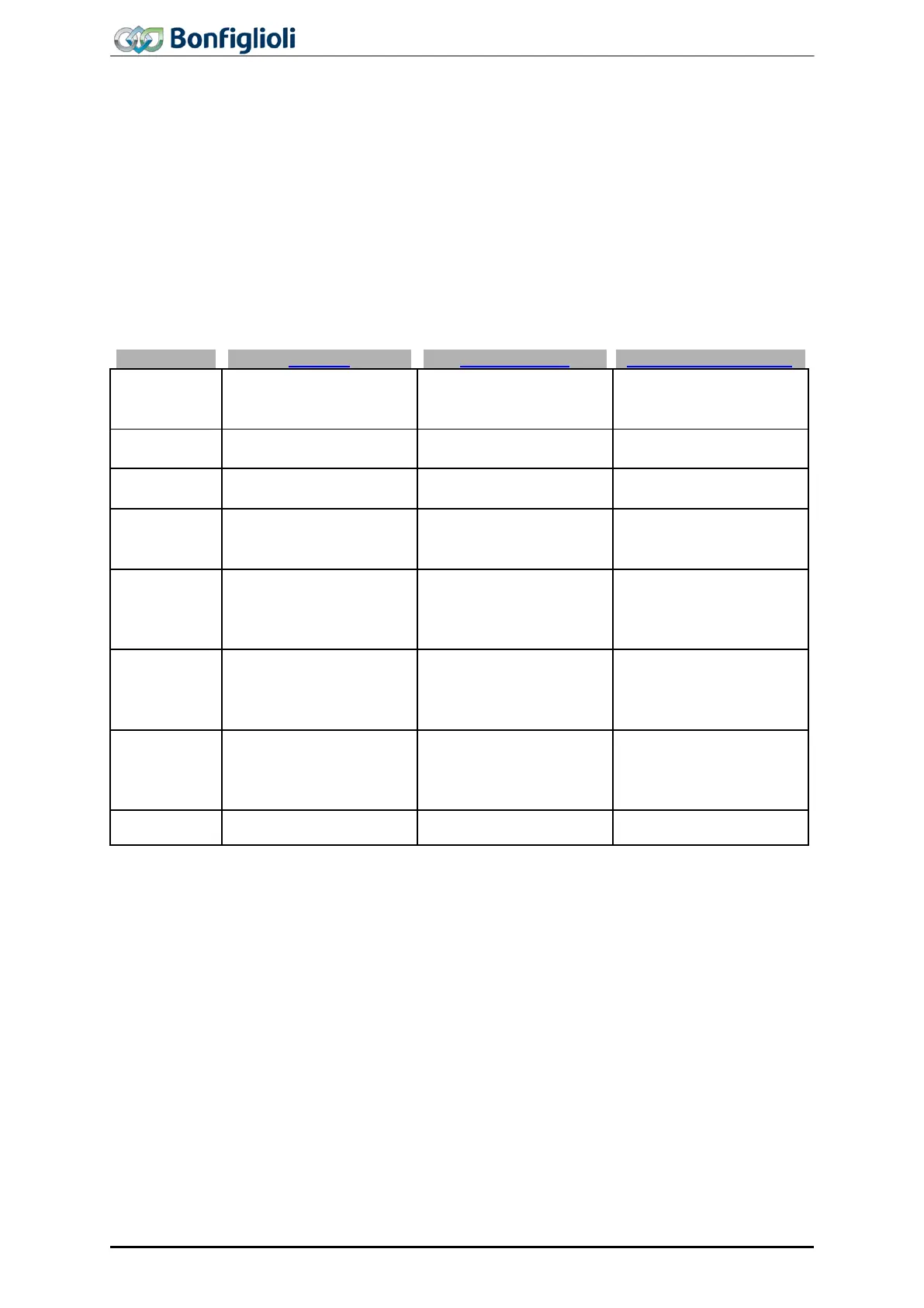
The following tables provide an overview of the different objects and parameters. The
object / parameter mentioned first in a cell will typically be used. If an object is related
to a parameter, the parameter will be specified.
The following tables show the available modes of Operation using the Motion Control
Override.
ride Modes
/
1459 Override Target
Velocity vl [rpm]
1460 Override Target Ve-
locity pv [u/s]
419 Maximum Frequen-
419 Maximum Frequen-
418 Minimum frequency
419
Maximum Frequency
(clockwise)
422 Acceleration anti-
1457 Override Accelera-
tion
(clockwise)
423 Deceleration anti-
1458 Override Decelera-
tion
stop
2)
Quick Stop
ramp
clockwise
425 Emergency stop
1) The limitation results from Minimum frequency 418 and Maximum Frequency 419. Through Limi-
tation
1118 of the position controller in Configuration x40, an increase above the Maximum Fre-
quency can occur, because the output of the position controller is added to the Maximum Frequen-
cy.
2) Emergency stop or Deceleration is used depending on the stopping behavior Mode of opera-
tion
630 or the behavior in the case of communication errors Bus Error Behaviour 388.
54
ACU
Modbus/TCP 10/13