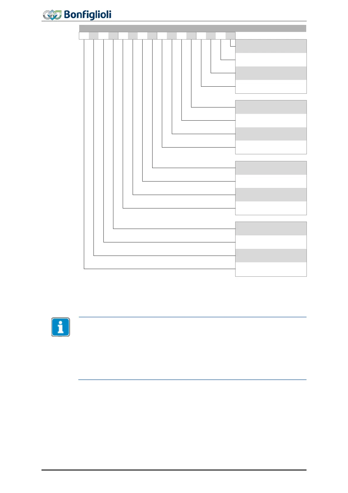
Manufacturer specific
Warning 2
Status word bits 12 and 13 “Operation mode specific” are only used in positioning con-
trol configurations (Parameter
30 = x40).
ACTIVE CUBE frequency inverters support an external 24 V power supply for the in-
verter control electronics. Even when mains voltage is
disconnected, communication
between the controller (PLC) and the frequency inverter is still possible.
Bit 4 “Voltage enabled” of the status word shows the current mains power supply st
tus:
Bit 4 Voltage enabled” = 0 signals “No mains voltage”, starting of drive not possible.
Bit 4 “Voltage enabled” = 1 signals “Mains voltage on”, drive ready for start.
68
ACU
Modbus/TCP 10/13