2-1
Bosch Security Systems 09/11 BLCC500I
S E C T IO N 2
Installing the Hardware
A BO UT T H E PA NE L
E NC LO SU RE S
The MW700 - Small Enclosure and MW710 - Large
Enclosure have been designed to reduce installation time
and improve aesthetics on larger installations where often
multiple enclosures need to be located in close proximity
to each other.
A number of new features have been incorporated
including a new style tamper bracket which can be
easily installed before or after the enclosure is mounted
to the wall, an anti tamper lid which insures the cabinet
tamper triggers when the lid is removed, easier access
for exible and rigid conduits, additional 20mm cable
entry knockouts and a new board mounting system using
removable spring clips.
The MW700 and MW710 enclosures include numerous
holes, allowing the PCB mounting clips to be positioned
in the most appropriate location for each installation.
For ease, it is recomended that the PCB mounting
clips are installed from the rear of the enclosure
before mounting it to the wall.
Circuit Board
Component Side
Rear of Cabinet
3mm Philips Head
Machine Screw
Supplied
Support Clip
Press Fit Supplied
Figure 1: PCB and Mounting Clip Installation Diagram
E NC LO SU RE FIX IN G ME TH O D
MW700 - Small Enclosure
Use appropriate fasteners capable of handling a minimum
of 6kg to x the cabinet against a sturdy surface using the
mounting holes provided.
MW710 - Large Cabinet
Use appropriate fasteners capable of handling a minimum
of 12kg to x the cabinet against a sturdy surface using
the mounting holes provided.
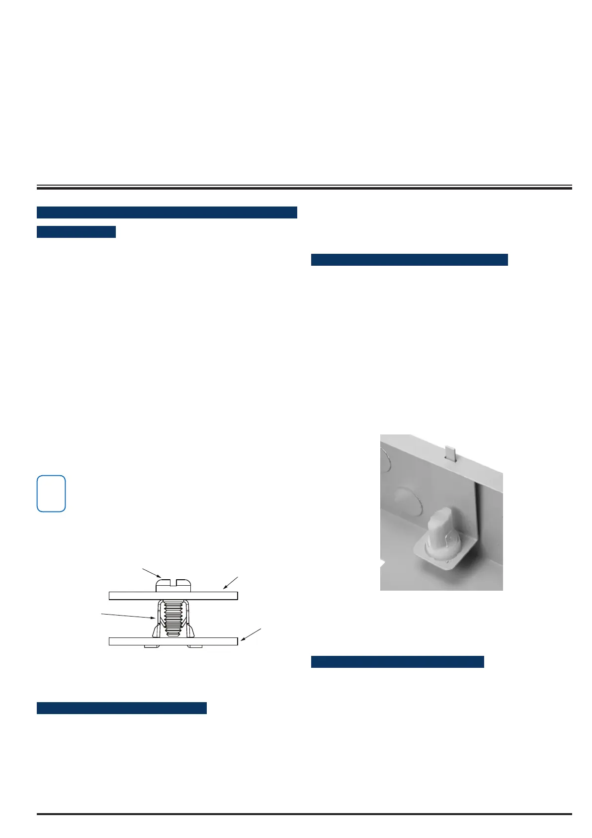
I NS TA LL IN G T HE TA MP ER S WI TC H
The tamper switch can be located on either the left or right
hand side of the cabinet to suit the installation. Before
installing the bracket, t the tamper lead to the switch
and then insert it into the bracket.
Once the enclosure has been mounted to the wall, insert
the tamper bracket into the rectangular hole in the top
ange of the enclosure and then slide the base of the
bracket toward the top until the tamper switch locates in
the rear of the enclosure.
Depress the tamper a few times with your nger to ensure
smooth operation.
Figure 2: Tamper Bracket Installation
E NC LO SU RE MOD UL E SPA CE S
The MW700 enclosure has space for 2 large modules or
4 small modules while the optional MW710 enclosure
has space for up to 4 large modules or 8 small ones. The
enclosures have been designed so that any combination
of large and small units can be neatly mounted together
on the wall.
Each module is mounted to the enclosure using 4 or more
clip in standos. The clips can be inserted from the rear
of the enclosure before mounting it to the wall, or from
the front of the enclosure after it has been mounted. Both