3-2
Bosch Security Systems 09/11 BLCC500I
Solution 16i
Installation Manual Wiring Diagrams
B OA RD CO NN E C TO RS
T
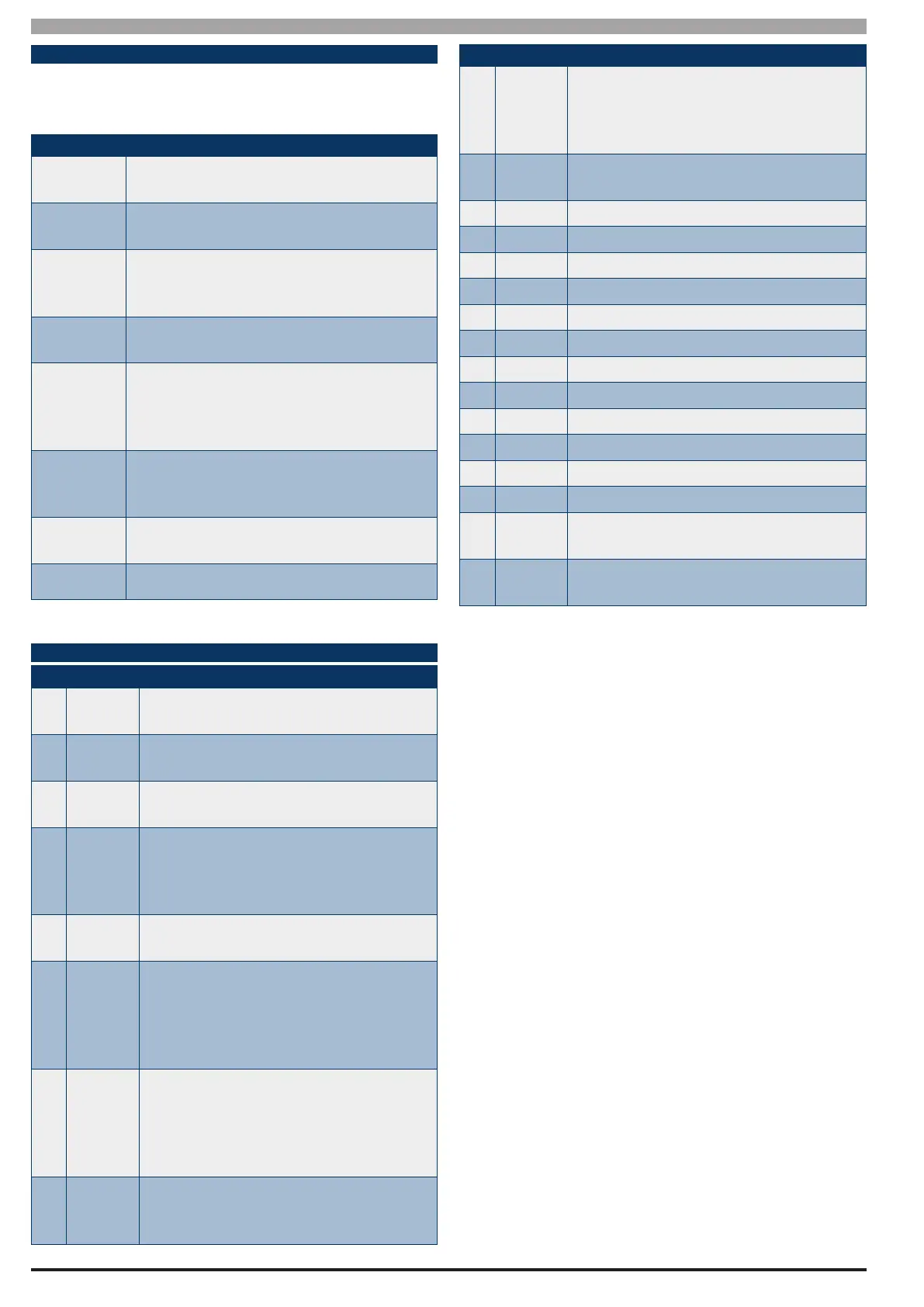
he following table lists the various sockets, pin headers
and switches located on the panel and their functions.
Connector
Description
Service
This socket allow you to connect a service
Keypad to the panel during installation.
Tamper
This socket is used to connect the cabinet
tamper switch to the panel.
Default
This push button is used to reset the con-
trol panel back to factory default and to
enable Direct Link Programming Mode.
Voice
Module
This is used to connect the optional Voice
Command Module (CM101B).
Direct Link
Port
This socket is used to connect the Direct
Link Interface (P/N CM900B) or the Flash
Programmer Interface (P/N CM901) to the
panel.
Telco
This is a RJ12 6P/4C connector that allows
you to connect the control panel to the
PSTN telephone line.
Expansion
Port
Used to connect addition modules to the
control panel. eg TCP/IP interface.
LAN Term Used to terminate the RS485 LAN.
Table 12: Board Connector Descriptions
T ER MI NA L DE SC R IP TI ON S
Nº Name Description
1 Earth
Earth wire from this terminal is
connected to the Mains earth.
2
3
~ (AC)
~ (AC)
Connection of the 16-18V AC 50-60 Hz
adapter or internal transformer.
4
5
BAT (-)
BAT (+)
Negative and positive connections to
the stand-by battery. 12 VDC / 7.2AH
6
7
8
9
+12 V
+12 V
GND
GND
These terminals are used to power
detectors and other accessory devices.
(750mA Fused)
10
11
LAN +
LAN -
These terminals are used to power LAN
modules and devices. (750 mA Fused)
12 LAN A
Connect the LAN A data terminal of any
LAN device (eg. Keypads, expansion
boards) to this terminal. The control
panel supports up to 300 m of 24/0.20
(18 AWG) wire on these terminals.
13 LAN B
Connect the LAN B data terminal of any
LAN device (eg. Keypads, expansion
boards) to this terminal. The control
panel supports up to 300 m of 24/0.20
(18 AWG) wire on these terminals.
14 COMM+
Common positive terminal for system
outputs. This terminal is 2.5A PTC Fuse
protected.
Nº Name Description
15
16
17
18
OUT 1
OUT 2
OUT 3
OUT 4
Fully supervised programmable, open
collector outputs capable of driving
(sink) loads up to 1 amp for sirens,
strobes etc.
19 INPUT
Programmable Input for RF Receivers,
Keyswitch and other devices.
20 ZN 1 Zone 1 and 9 sensor loop input (+).
21 GND Common (-) for Zone 1 & 2 sensor loop.
22 ZN 2 Zone 2 and 10 sensor loop input (+).
23 ZN 3 Zone 3 and 11 sensor loop input (+).
24 GND Common (-) for Zone 3 & 4 sensor loop.
25 ZN 4 Zone 4 and 12 sensor loop input (+).
26 ZN 5 Zone 5 and 13 sensor loop input (+).
27 GND Common (-) for Zone 5 & 6 sensor loop.
28 ZN 6 Zone 6 and 14 sensor loop input (+).
29 ZN 7 Zone 7 and 15 sensor loop input (+).
30 GND Common (-) for Zone 7 & 8 sensor loop.
31 ZN 8 Zone 8 and 16 sensor loop input (+).
32
33
IN
IN
These terminals are used to connect the
telephone line from the street.
34
35
OUT
OUT
These terminals are used to connect the
premises telephones.
Table 13: Terminal Block Descriptions and Functions