2-6
Bosch Security Systems 09/11 BLCC500I
Solution 16i
Installation Manual Installing the Hardware
Figure 8: Keypad Emergency Keys
KEYPAD E MERG ENC Y A LARM TRIGGER ’S
Key Sequence Event Triggered
[←] + [→] Hold for 2 seconds Keypad Fire Alarm
[→] + [↑] Hold for 2 seconds Keypad Panic Alarm
[↑] + [↓] Hold for 2 seconds Keypad Medical Alarm
Table 5: Keypad Emergency Alarm Trigger’s
K EYPA D SE T UP
The Solution 16i control panel can have a maximum of 8
keypads connected via the LAN terminals. Each keypad
must be set to a unique address before they will operate.
Each keypad needs to be assigned to a home area via
MENU 6-1-3. This sets the area the keypad will display and
control by default. Keypads can be locked to a home area
or allowed to roam or move between areas.
When the system is powered up, any keypads which have
not been assigned a home area will be automatically set
to home area 1.
Set each keypad address using the table below as a guide.
Only 1 Keypad can be assigned to each address. All
Keypads are supplied from the factory set to address
1. (OFF-OFF-OFF-OFF).
K EYPA D AD DRE SS SEL EC T IO N
4
Figure 9: Keypad Address Selection
Keypad DIP Switch Address Settings
Keypad To
Address
S1 S2 S3 S4
Keypad 1 O O O O
Keypad 2 On O O O
Keypad 3 O On O O
Keypad 4 On On O O
Keypad 5 O O On O
Keypad 6 On O On O
Keypad 7
O On On O
Keypad 8 On On On O
Table 6: Keypad DIP Switch Address Settings
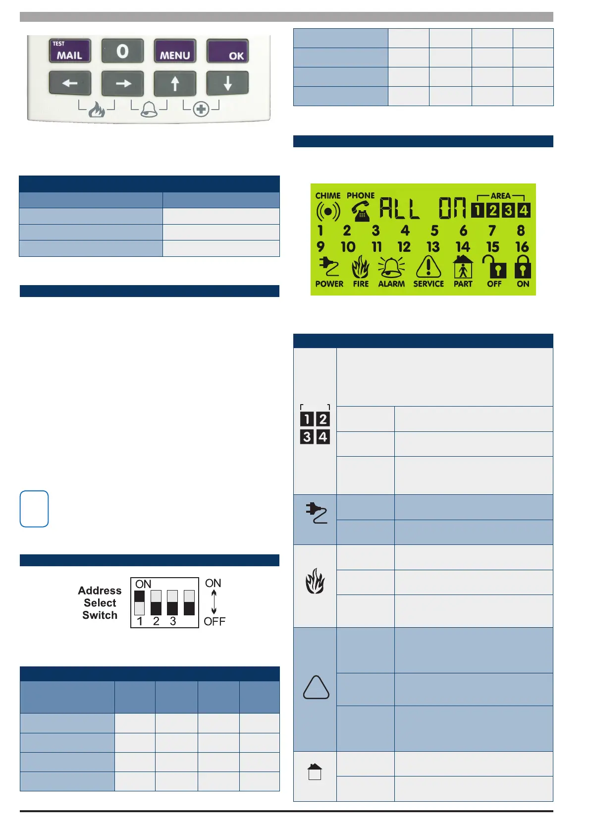
S TAT US I CO NS & LE D I N DI CATO RS
The following table lists the function of each of the ICON
Symbols and LED Indicators on the ICON Keypad Display.
Figure 10: LCD Display Showing All ICONs
Icon
Status Meaning
The keypad can display which areas (1 – 4) are
turned on or o via the Area Icon Indicators.
This programmable option can be disabled in
MENU 6-1-4.
On Area is turned All On or Part On
O Area is turned O
Flashing
Fast
Alarm occurred in the area
On System power is normal
Flashing System power is missing
Flashing A re alarm is active
O
No re alarm
On
Fire alarm in memory (Turn the
area All On and O to Clear).
!
On
The existing service or trouble
condition has been acknowl-
edged.
O
No service or trouble conditions
exist
Flashing
A service or trouble condition
is present that has not been
acknowledged.
M
PART
On The area is turned Part On.
O The area is not turned Part On.