2-3
Bosch Security Systems 09/11 BLCC500I
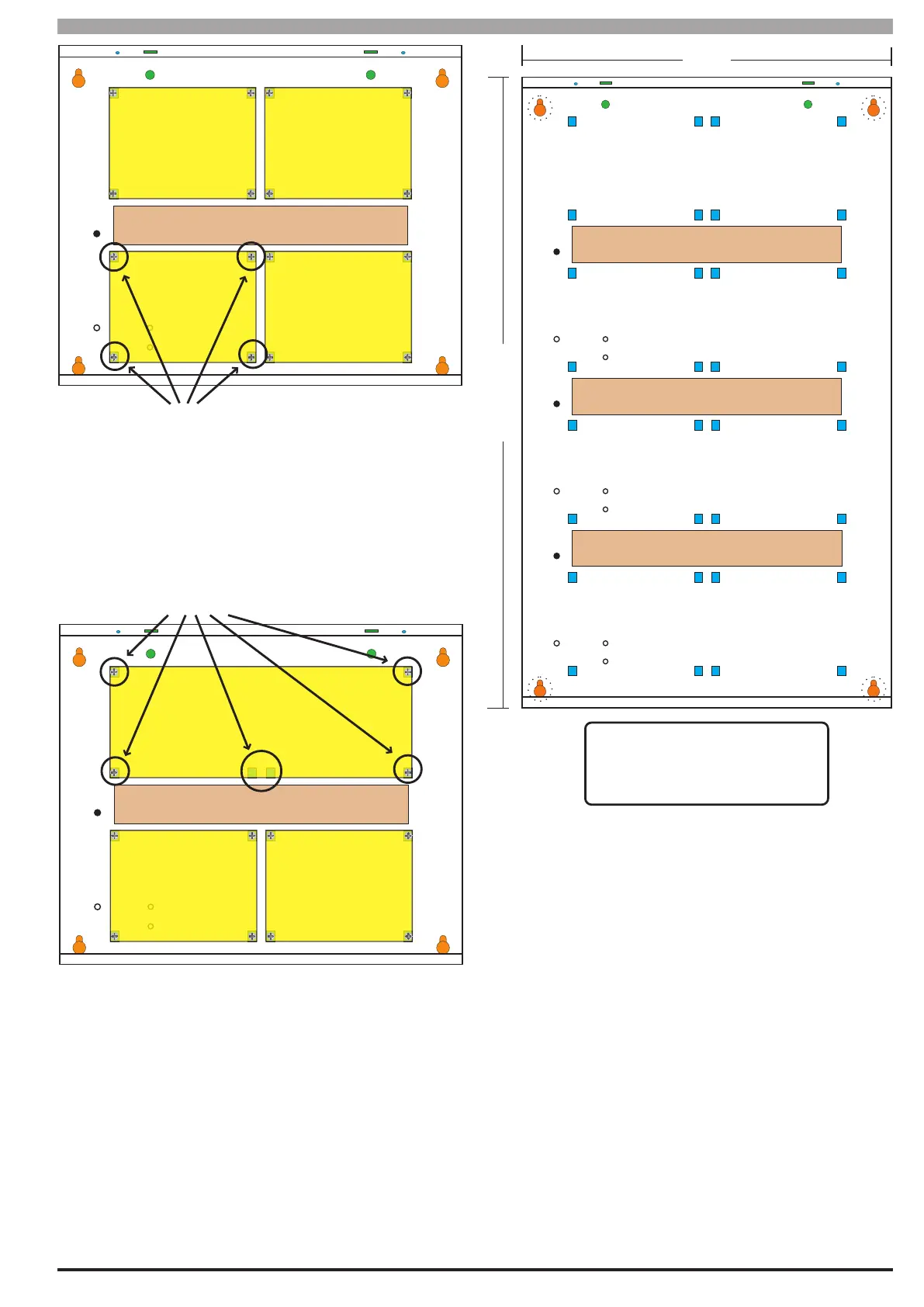
Solution 16i
Installation Manual Installing the Hardware
CABLE ENTRY (REAR)
MODULE
SPACE 1
MODULE
SPACE 4
MODULE
SPACE 2
MODULE
SPACE 3
CABLE ENTRY (REAR)
MODULE
SPACE 1
MODULE
SPACE 3
MODULE
SPACE 2
When installing small modules, you should
fit 4 mounting clips as shown.
1
2
3
4
1
2
3
4
5
When installing large modules, you should
fit 5 mounting clips as shown.
Clip 5 provides support under the main
terminal block only. No screw is fitted.
Figure 4: MW700 Conguration Examples
320 mm
520 mm
A A
A
A
AAAA
A AAA
A
AAA
A AAA
A
AAA
A AAA
A
AAA
CABLE ENTRY (REAR)
CABLE ENTRY (REAR)
CABLE ENTRY (REAR)
A
= PCB Mounting Clip Holes
= Enclosure Mounting Holes
B
= Tamper Bracket Mounting Holes
C
= Earth Stud - 4mm
D
C C
BB
D
BB
D
D
Figure 5: MW710 - Large Enclosure Details
The following examples show the MW710 - Large
enclosure congured using 6 small modules and 1 large
module.

 Loading...


