2-9
Bosch Security Systems 09/11 BLCC500I
Solution 16i
Installation Manual Installing the Hardware
E XPA N SI ON M OD UL ES
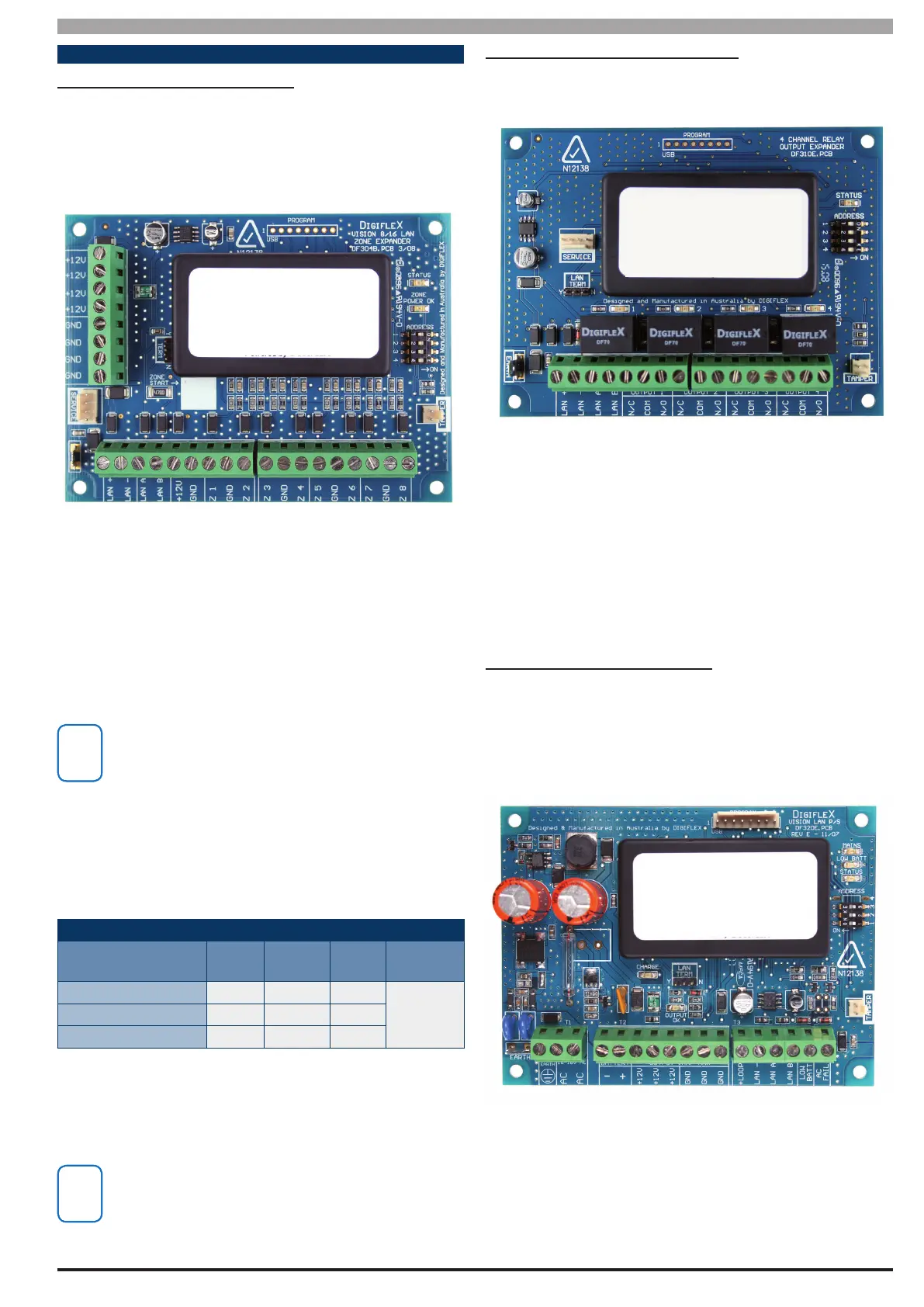
CM704B Zone Expander Module
The Solution 16i panel includes support for 1 x CM704B -
8/16 Zone Expansion module. This allows for 16 individual
zones when using Alarm and Tamper (4 state) monitoring
as well as allowing zones to be located in two separate
locations within a building.
Figure 13: CM704B Zone Expander
All zones follow the global EOL setting in MENU 3-4-0
regardless of whether they are on the panel or on the
expander module.
Zone numbering is automatically assigned by the panel
during power up depending on the module conguration
found and the EOL value selected.
When using the CM704B you should not select Split
EOL monitoring. If you do the zones on the expander
will not be available.
For example single EOL is selected and 1 x CM704B Zone
Expander is tted, then Zones 1 - 8 will be located on the
main panel and Zones 9 - 16 will be located on CM704B.
Fitting an RF receiver to the panel allows any zone to be
programmed as a wireless zone.
ZONE CONFIG UR ATION TABLE
Device Type
Single
EOL
Alarm +
Tamper
Split
EOL
RF
Zones
Solution 16i Panel 8 8 16
Up to
16 zones
Max
CM704B Expander 8 8 N/A
Total Zones 16 16 16
Table 9: Zone Conguration Using Expanders
Once a zone has been programmed to be a wireless type
the coresponding hardwired zone input is automatically
disabled. No EOL resistor is required.
Currently the panel supports only supports CM704B
zone expanders.
CM710B Output Expander Module
The Solution 16i panel includes support for 1 x CM710B, 4
Way Relay Output Expander.
Figure 14: CM710B Output Expander Module
Adding a CM710B adds an additional 4 relay outputs
to the panel. The maximum output capacity is 8. The
output expander can be located with the control panel
or in separate part of the building and then wired back
to the control panel via the 4 wire LAN to minimise cable
requirements.
CM720B Power Supply Module
The Solution 16i panel includes support for 1 x CM720B,
1 Amp LAN Power Supply Module which can be used to
provide LAN voltage regeneration as well as supplying
power to other modules, Intrusion Sensors Door Strikes
etc.
Figure 15: CM720B Power Supply Module
The CM720B module can be located with the control
panel or in separate part of the building and then wired
back to the control panel via the 4 wire LAN to minimise
cable requirements.

 Loading...


