3-1
Bosch Security Systems 09/11 BLCC500I
S E C T IO N 3
Wiring Diagrams
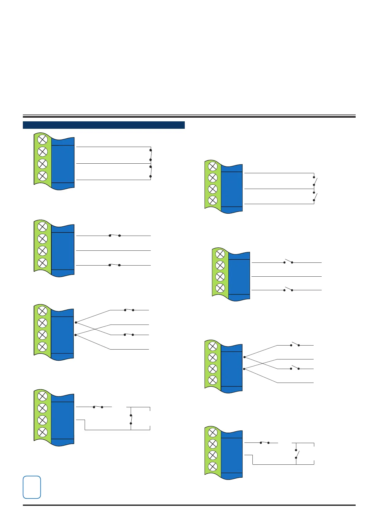
ZO NE W I RI NG
ZONE 2
N/C
N/C
ZONE 1
ZN 1
GND
ZN 2
Figure 20: N/C No EOL Zone
ZONE 2
ZONE 1
N/C
N/C
ALARM
ALARM
ZN 1
GND
ZN 2
Figure 21: N/C Single EOL Zone
(6K8 EOL)
(3K3 EOL)
N/C
ALARM
ALARM
ZN 1
GND
ZN 2
ZONE 1
ZONE 9
Figure 22: N/C Split EOL Zone
1
2
TAMPER
(6K8 EOL)
TAMPER
(3K3 EOL)
N/C
N/C
ZN 1
GND
ZN 2
ALARM
ZONE 1
Figure 23: N/C Zone With Tamper
The Above diagrams display the zone wiring
congurations using Normally-Closed Alarm
contacts and Normally-Open Alarm Contacts. When
using Normally-Open Alarm Contacts you must
select Inverted Seal for each zone in MENU 3-1-8.
A shorted loop is a tamper condition for all EOL zone
congurations.
2
ZONE 2
N/O
N/O
ZONE 1
ZN 1
GND
ZN 2
Figure 24: N/O No EOL Zone
ZONE 2
ZONE 1
N/O
N/O
ALARM
ALARM
ZN 1
GND
ZN 2
Figure 25: N/O Single EOL Zone
(6K8 EOL)
(3K3 EOL)
N/O
N/O
ALARM
ALARM
ZN 1
GND
ZN 2
ZONE 9
ZONE 1
Figure 26: N/O Split EOL Zone
TAMPER
(6K8 EOL)
TAMPER
(3K3 EOL)
N/C
N/O
ZN 1
GND
ZN 2
ALARM
ZONE 1
Figure 27: N/O Zone With Tamper

 Loading...


