2-2
Bosch Security Systems 09/11 BLCC500I
Solution 16i
Installation Manual Installing the Hardware
methods should be performed using your nger tips to
prevent damage to the stando. (Standos and screws
are supplied with each module).
All compatible add on modules will mount on these
spaces. See below for list if modules which can be added
to the Solution 16i control panel.
Module Space Occupied
Solution 16i Control Panel 2 Module Spaces
CM704B Zone Expander 1 Module Space
CM710B Output Expander 1 Module Space
CM720B LAN Power Supply 1 Module Space
CM195 RF Receiver Expander 1 Module Space
Table 1: Expansion Options
Use the above table to help determine which size cabinet
you will require for the job.
On some export models, one module space will not be
available as the mains transformer mounts in this location.
I NS TA LL IN G PANE LS A N D M OD U LE S
Once the enclosure is secured in place, install the panels
and modules onto the mounting clip using the supplied
3mm screws. Do not over tighten the screws.
When tting panels or large modules, you should use 5
mounting clips, one in each corner of the PCB and one
in the middle of the PCB underneath the main terminal
blocks. When mounting small modules, only 4 clips are
required, 1 in each corner.
Both enclosures are supplied with tamper switches,
tamper leads, tamper brackets and a quantity of
mounting clips and screws. If required, additional
mounting clips and screws may be purchased in bags of
50 clips (10 packs x 5pcs). (P/N: MW890)
The supplied mounting clips are designed to use the
3mm machine screws supplied with the enclosure.
The use of self tapping screws will damage the clips.
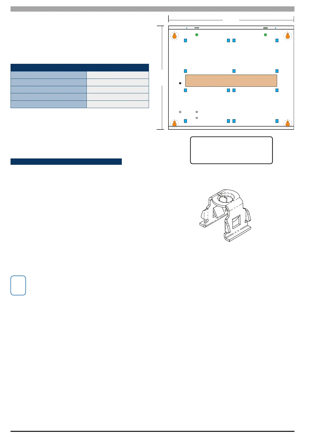
320 mm
260 mm
A AAA
A
AAA
CABLE ENTRY (REAR)
A A
A
A
AAAA
A
= PCB Mounting Clip Holes
C C
BB
B
B
D
= Enclosure Mounting Holes
B
= Tamper Bracket Mounting Holes
C
= Earth Stud - 4mm
D
Figure 3: MW700 - Small Enclosure Details
Figure 3: PCB Mounting Clip
The following example shows the MW700 -Small enclosure
congured using 4 small modules.

 Loading...


