9E-926 46 SmartControl™ Meter & TouchPoint™
Operation Instructions
4. Operation
4.1 Understanding Basic Parts
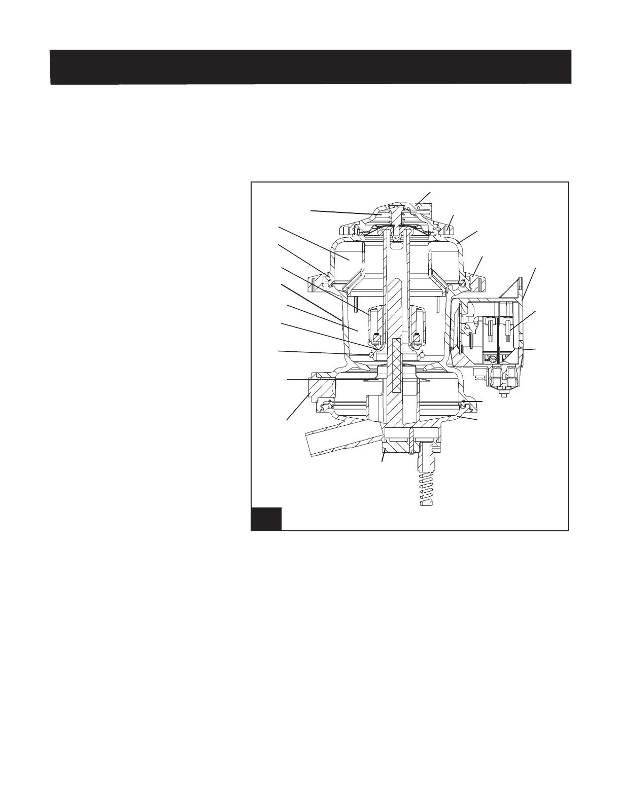
4.1.1 Milk Meter
The milk meter measures a cow’s milk production, milking time
and conductivity—all of which it sends to a SmartDairy Control-
ler (if used). The meter consists of the parts shown in Figure
30.
30. Section view of meter l925_11
Top Cap
Cap Lock
Ring
Inlet
Section
Inlet Lock
Ring
Mounting
Box
Solenoid
Valve
Junction
Box Cover
Gasket
Outlet
Section
Conductivity
Probes
(Not Shown)
Level Sensing
Probe
Sampler
Plug
Wash
Deector
Plunger
Seal
Plunger
Measuring
Chamber
Mounting
Strap
Float
Assy
Gasket
Bafe
Diaphragm and
Spring Assy
Milk meter operation begins when milk and air from the claw
enter the inlet of the meter. A bafe in the upper section of the
meter separates the air from the milk and directs the milk down
the inside wall of the measuring chamber (to reduce foaming),
while air escapes through the air bypass. This separation al-
lows the meter to maintain a stable vacuum level.
Attached to the top of the inlet is a small chamber containing
a diaphragm and spring assembly. These parts raise and lower
the plunger to empty and ll the chamber as determined by the
electronic control.
The measuring chamber contains a seat, a plunger with rubber
sealing surface and a sealed oat with a magnet inside. This
chamber is transparent and cylindrical.