SmartControl™ Meter & TouchPoint™ 9 9E-926
Operation Instructions
LED Status Indicators
The LED Status Indicators will show the status of the Smart
Control Meter (see Tables 1 and 2 for colors used during “Milk-
ing” or “Washing” modes). The LEDs are visible from the side
of the Smart Control Meter.
Milk Conductivity
The SmartControl will measure the milk conductivity when a
cow is being milked.
Milk Sampler Port
The milk sampler port allows a milk sample to be taken when
a cow is being milked.
Magnetic Switch
The Magnetic Switch is used during the addressing of the con-
trol. It can also be used as an alternative method to place the
control in the attached mode or place it in the wash mode.
Milk Inlet
The Milk Inlet is the input of the meter vessel. The inlet comes
in two styles: right or left input.
Milk Outlet
The Milk Outlet is the output of the meter vessel.
Circuit Board Enclosure
The control enclosure contains the circuit board and valves
that are used to measure and control the operation of the me-
ter assembly.
The TouchPoint and SmartControl Meter have colored LED indi-
cators that are used for indicating the different modes of oper-
ation or conditions of each control. The TouchPoint can display
the following colors: white, green, yellow, red, dark blue, pink
and violet. The SmartMeter can display only red and yellow.
See Figures 1 and 2 for the location of the LED indicators and
Tables 1 and 2 for the color and pattern.
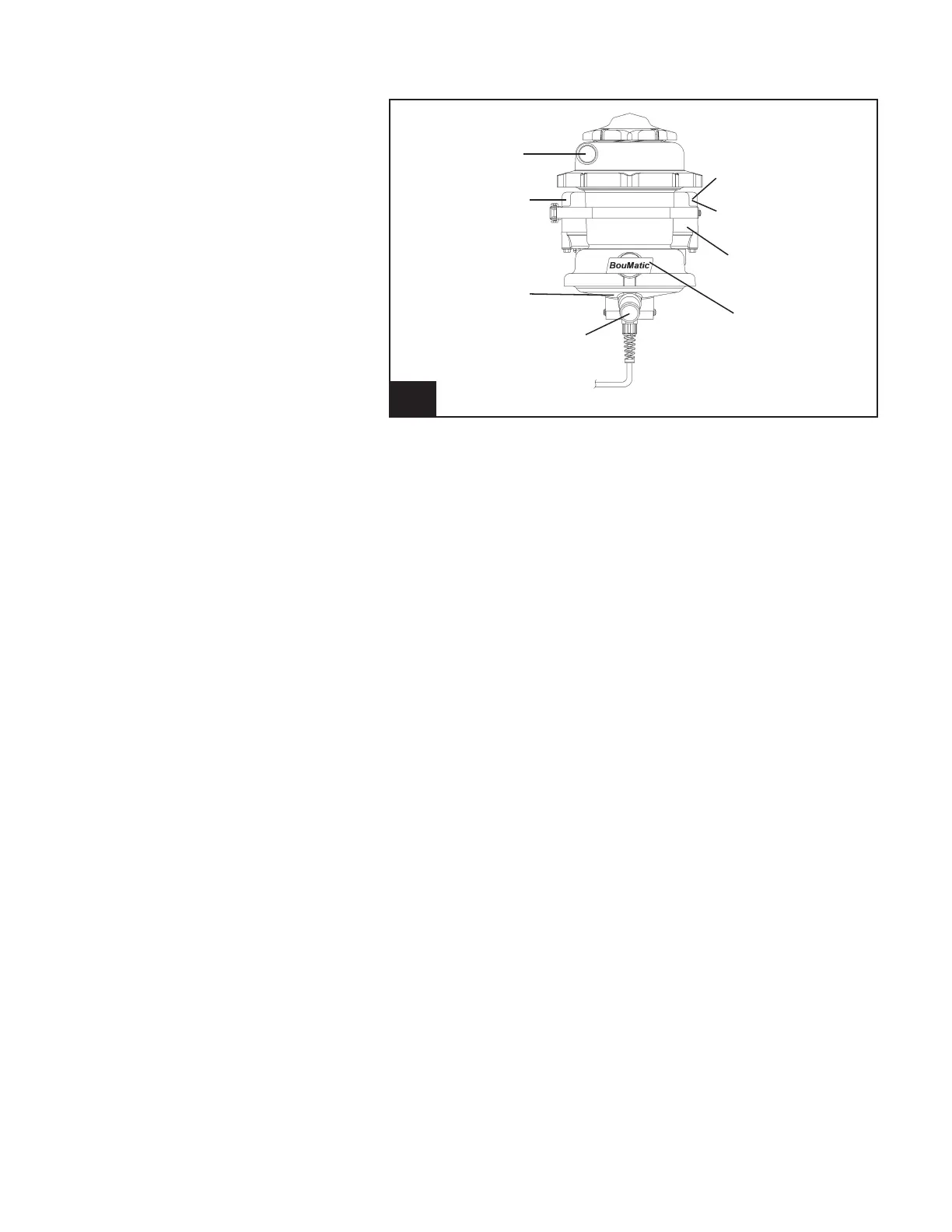
2.1.3 SmartControl Meter Overview
2. SmartControl Meter Overview l926_2
Milk Inlet
Yellow LED Status
Indicator
Milk Conductivity
Milk Outlet
Red LED Indicator
Magnetic Switch
Circuit Board
Enclosure
Milk Sampler Port