9E-926 72 SmartControl™ Meter & TouchPoint™
Operation Instructions
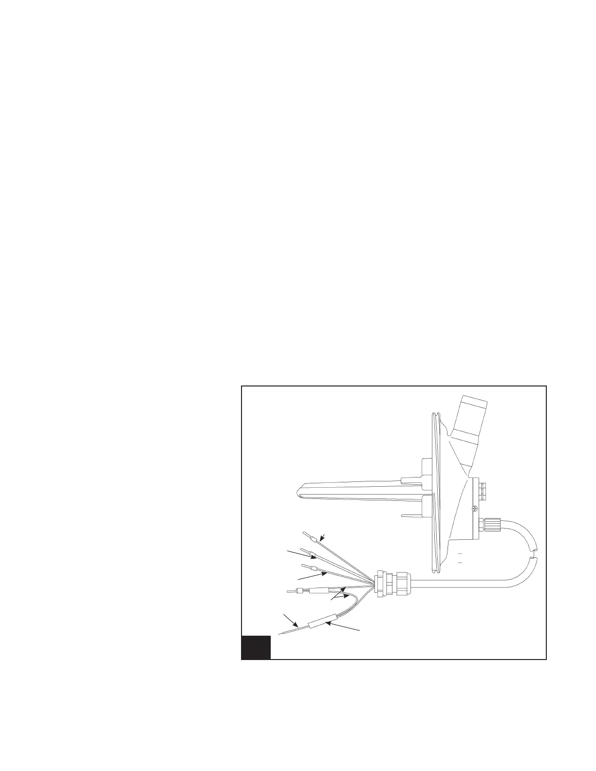
33. Meter Outlet, Two Sensors l925_14
Orange
Black
White
Red
Blue
PWB ASSY
Power Adapter
7.6.2 Meter Outlet, Two Sensors
1. Turn power off the control that is going to be replaced.
2. Disconnect the ve wires from J4.
3. Remove the old meter outlet.
4. Install the new meter outlet.
5. Remove the black module connected to the blue wires.
a. Connect the blue wire to J7, pin 7 or pin 9. It may be
necessary to add a short section of wire to reach J7.
6. Connect the four wires to J4.
a. J4, pin 1 DC common red
b. J4, pin 2 Input – level sensor orange
c. J4, pin 3 Conductivity black
d. J4, pin 4 Conductivity white
7. Secure the four screws on the base. You should retighten
the rst two screws to seal the assembly.
8. Turn power back on.
9. Verify the operation of the SmartControl Meter by observ-
ing the milking of a minimum of three cows.