SmartControl™ Meter & TouchPoint™ 71 9E-926
Operation Instructions
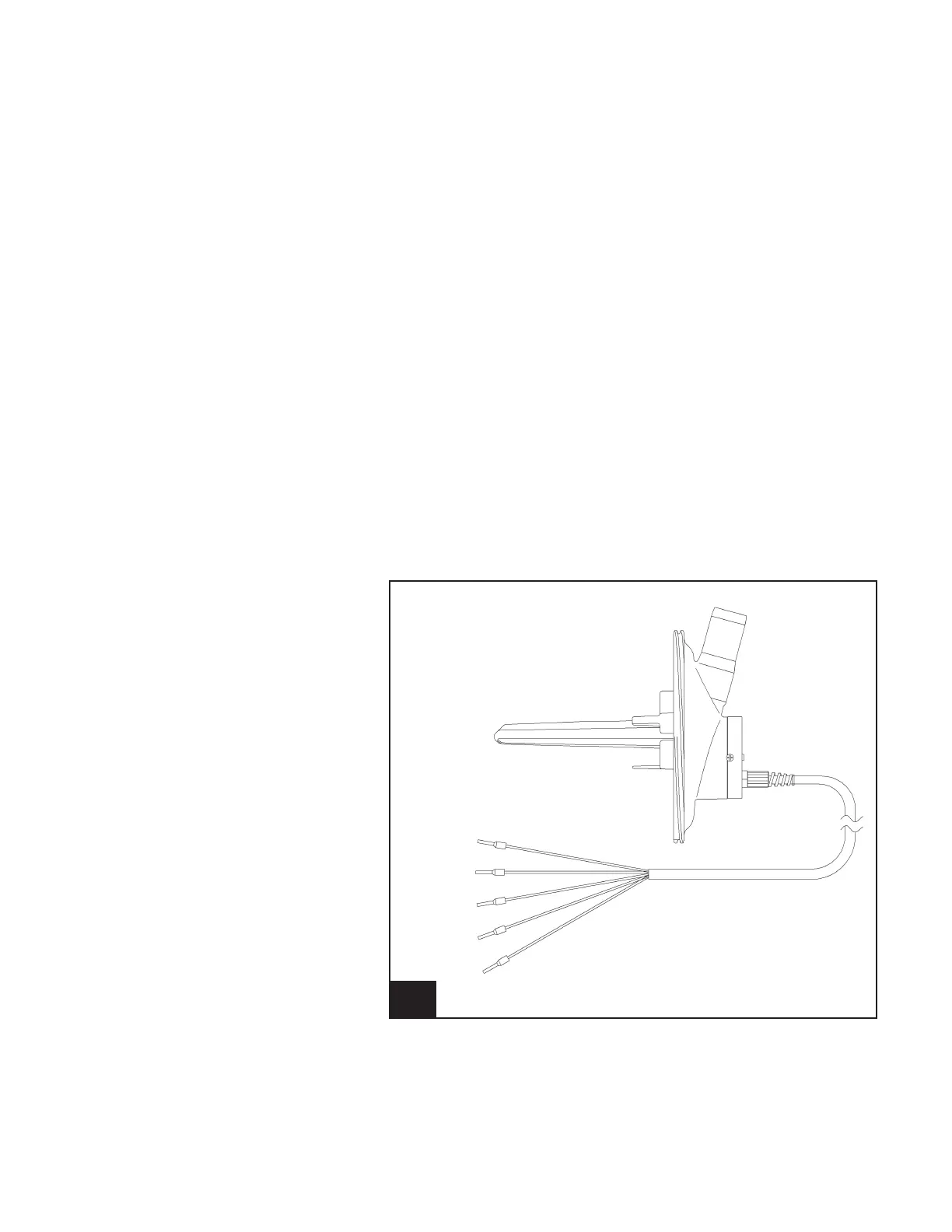
7.6.1 Meter Outlet, One Sensor
1. Turn power off to the control that has the meter outlet that
is going to be replaced.
2. Disconnect the ve wires from J4.
3. Remove the old meter outlet.
4. Install the new meter outlet.
5. Connect the ve wires to J4.
a. J4, pin 1 DC common red
b. J4, pin 2 Input – level sensor orange
c. J4, pin 3 Conductivity black
d. J4, pin 4 Conductivity white
e. J4, pin 5 + DC voltage – level yellow
6. Secure the screws on the base. You should retighten all the
screws again to seal the assembly.
7. Turn power back on.
8. Verify the operation of the SmartControl Meter by observ-
ing the milking of a minimum of three cows.
32. Meter Outlet, One Sensor l925_15
White
Black
Orange
Red
Yellow