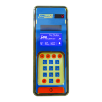
SmartControl™ Meter & TouchPoint™ 35 9E-926
Operation Instructions
3. Features
3.1 TouchPoint Milking System
Each control contains a microcontroller that operates over 14
MIPS (14 Million Instructions Per Second) to give fast and ac-
curate control of all the milking functions. This speed allows
continuous monitoring of the milk production during the milk-
ing of a cow (while providing optional pulsation for each cow).
The TouchPoint milking system uses the BouMatic PRISM Net-
work to send milking data to a SmartDairy™ Controller, ad-
just the various parameters that control the milking of a cow,
and remotely update the software that controls the TouchPoint
milking system.
The TouchPoint milking system has over 36 parameters to help
provide optimal milking performance. Some of the parameters
are: Take Off Flow Rate, Let-Down Delay, Takeoff Delay, Claw
Drop, Claw Lift, Claw Lift Time Out, Reattach Delay, Maximum
Milking Time, optional pulsation, etc.
3.2 Features and Parameter Settings
The parlor and milking parameters are adjusted at the dealer
or dairyman’s PC and use the PRISM networks to adjust all the
parameters at the same time. If a SmartDairy Controller is be-
ing used on the dairy the parameter changes are sent by the
SmartDairy™ Controller. The same PRISM network is also used
to upgrade the software in each control. Changing the software
typically takes less than ve minutes for the entire parlor for
each control type. All parameters are stored in the controls so
that in the case of a power outage they are available immedi-
ately when power is restored.
The SmartControl Meter does most of the work of recording the
milk production, controlling the milk shutoff, takeoff ow rate,
conductivity, etc. The TouchPoint is primarily used to display
the milk production and accept commands from the milkers.
Each control contains the following major sections: microcon-
troller, communication circuit and auxiliary inputs and outputs.
All inputs and outputs have LED indicators to help with trouble-
shooting (see Tables 2a, 2b, 2c, 2d, and Figures 27a and 27b
for an explanation of the connectors and LED indicators). All
auxiliary outputs have protection for shorts. If a fault occurs
the short should be removed and the output turned off, then
back on, to reset the protection circuitry.