6-26 Confidential
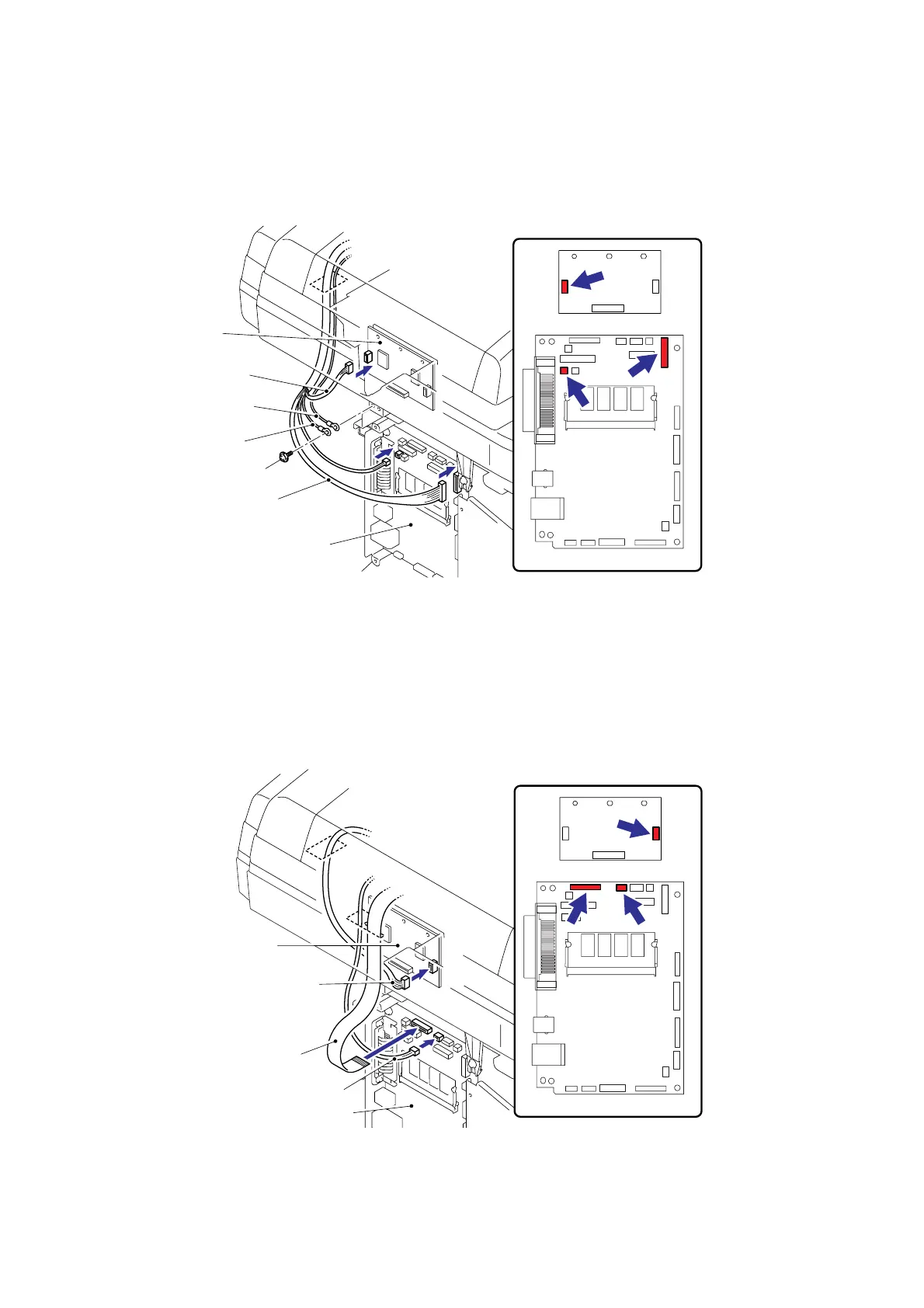
(18) Connect the two Connectors into the Main PCB.
(19) Connect the Connector into Driver PCB.
(20) Secure the ADF FG harness and FB FG harness with the cup S M3x6 Taptite screw.
Fig. 6-46
(21) Connect the connectors of the Photo interrupter and FFC cable into the Main PCB.
NOTE:
When connecting flat cable(s), do not insert them at an angle. After insertion, check that the
cables are not at an angle.
(22) Connect the connector of the Scanner motor harness into the Driver PCB.
Fig. 6-47
Driver PCB
Connector
(ADF motor harness)
FB FG harness
ADF FG harness
Main PCB
Connectors
(ADF relay harness)
Taptite, cup S M3x6
Driver PCB
Scanner motor harness
FFC cable
Photo interrupter
Main PCB
Main PCB
Driver PCB
Main PCB
Driver PCB
 Loading...