160
OILING SYSTEM
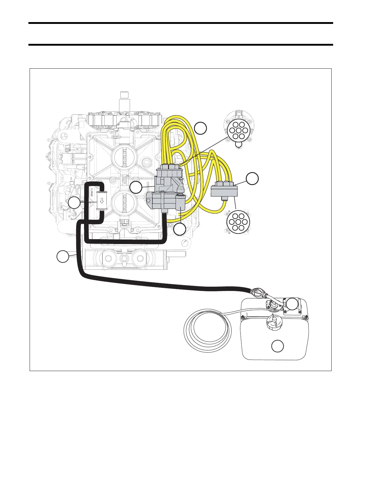
OIL SUPPLY DIAGRAMS – V4
OIL SUPPLY DIAGRAMS – V4
1.
2.
3.
4.
5.
6.
7.
8.
Oil tank assembly
Oil pick-up
Oil supply hose
In-line oil filter
Oil injector assembly
Oil distribution hoses
Oil pressure sensor
Rear oil manifold
Rear oil manifold delivers oil to:
- #1, #2, #3 and #4 cylinder sleeves
Primary oil manifold delivers oil to:
- Rear oil manifold
- #1, #2, #3 and #4 crankcase fittings
7
5
6
8
1
2
3 4
5
Primary Oil
Manifold
Rear Oil
Manifold
1
2
3 4
1. Cylinder 2
2. Cylinder 4
3. Cylinder 3
4. Cylinder 1
1. Cylinder 4
2. Cylinder 1
3. Cylinder 2
4. Cylinder 3
5. Auxliary oil manifold
1. Oil tank assembly
2. Oil pick-up
3. Oil supply hose
4. Oil filter
5. Oil pump assembly
6. Oil distribution hoses
7. Oil pressure switch
8. Auxiliary oil manifold
1
2
3
4