184
COOLING SYSTEM
HOSE ROUTING AND WATER FLOW DIAGRAMS
HOSE ROUTING AND WATER FLOW DIAGRAMS
V4 MODELS
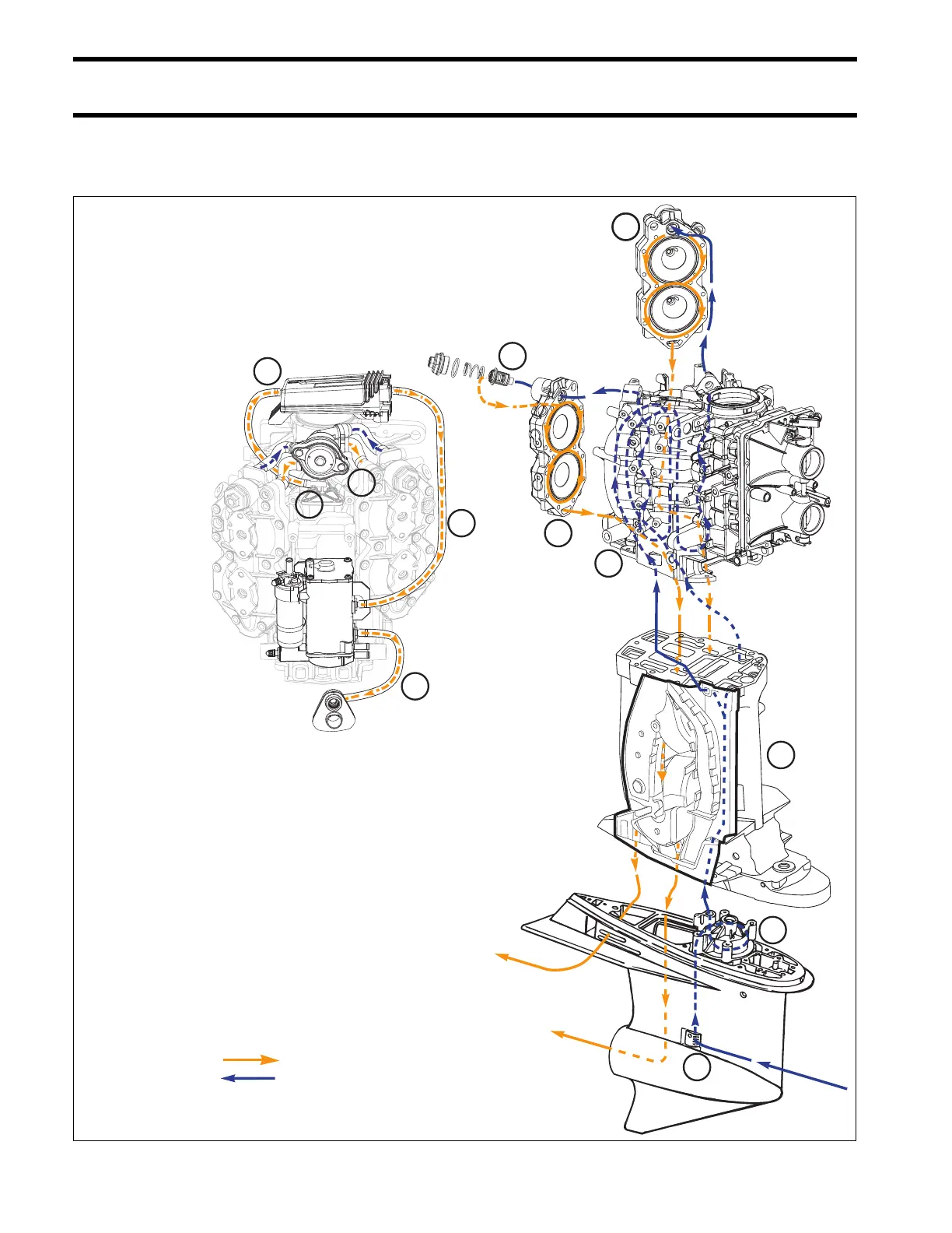
Hose Routing & W ater Flow Diagra m
115H.O. – 130HP/60°V4
Outgoing water (warm/hot)
Incoming W ater (cool )
1. W ater intake screen s
2. W ater pum p
3. Exhaust housing
4. Cylinder block
5. Thermostat
6. Pressure valve
7. Cylinder head, water outlet
8. Cylinder block vent
9. W ater supply to EMM
10. W ater suppl y , EMM to vapor separator
1 1. Vapor separator to overboard indicator
5
5
7
9
10
11
6
8
1
3
2
4
1.
2.
3.
4.
5.
6.
7.
8.
9.
10.
11.
Water intake screens
Water pump
Exhaust housing
Cylinder block
Thermostat
Pressure valve
Cylinder head, water outlet
Cylinder block vent
Water supply to EMM
Water supply, EMM to vapor separator
Vapor separator to overboard indicator
Outgoing water (warm/hot)
Incoming water (cool)