217
POWERHEAD
POWERHEAD ASSEMBLY
10
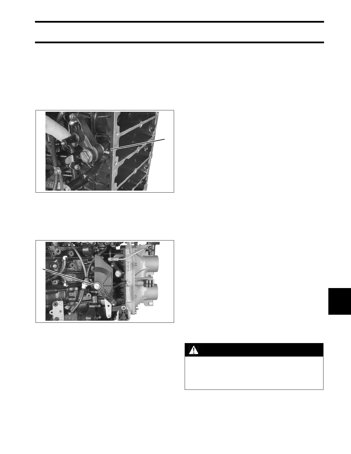
Throttle Linkage Installation
Apply Nut Lock to threads of throttle lever screw.
Insert spring into cavity of throttle lever.
Install lever, screw, and washer on crankcase and
hook spring on rib as shown. Tighten screw to a
torque of 120 to 144 in. lbs. (13.5 to 16.5 N·m).
Apply Nut Lock to threads of throttle cam screw.
Install cam, screw, and washer on cylinder block
and tighten screw to a torque of 120 to 144 in. lbs.
(13.5 to 16 N·m).
IMPORTANT: Do not lubricate throttle levers or
shoulder screws.
Final Powerhead Assembly
Install the reed plate and throttle body assemblies.
Refer to Intake Manifold Service on p. 153.
Install oil recirculating hoses and check valves.
Refer to OIL RECIRCULATION DIAGRAMS – V4
on p. 164, OIL RECIRCULATION DIAGRAMS –
V6 on p. 166, or POWERHEAD VIEWS on p. 223.
Install pressure valve assembly. Refer to PRES-
SURE RELIEF VALVE SERVICING on p. 192.
Install shift linkage. Refer to Shift Linkage Instal-
lation on p. 216.
Install throttle linkage. Refer to Throttle Linkage
Installation on p. 217.
Install fuel injectors and ignition coils. Refer to
Fuel Injector Installation on p. 151.
IMPORTANT: All injectors must be reinstalled in
their original location. Improper injector installation
can result in powerhead failure.
Install oil pump, rear oil manifold, and oil injection
hoses. Refer to OIL COMPONENT SERVICING
on p. 179.
Install flywheel and stator. Refer to FLYWHEEL
AND STATOR SERVICING on p. 110.
Install electrical harness with flywheel cover base,
starter solenoid, and trim relay module, then
install EMM. Refer to EMM SERVICING on p. 68.
Install fuel pump assemblies, fuel manifolds, and
filter. Refer to FUEL COMPONENT SERVICING
on p. 146.
Install the electric starter. Refer to Starter Instal-
lation on p. 123.
1. Throttle lever spring 005259
1. Throttle cam screw 005293
WARNING
To prevent fire and explosion hazard,
make sure all electrical and ignition wiring
is routed and clamped in original posi-
tions.