342
TRIM AND TILT
TRIM AND TILT REPLACEMENT
Trim Sender Test
IMPORTANT: To avoid immediate meter dam-
age, never apply a multimeter to an electrical cir-
cuit where voltage is present.
Disconnect the 3-pin connector between the
instrument harness and engine trim harness.
Connect an ohmmeter between the white/tan wire,
terminal “C,” of the engine harness and a clean
engine ground.
With the outboard fully DOWN, meter must show
a reading above 80 W.
With the outboard fully UP, meter must show a
reading below 10 W.
• If results agree, refer to Trim Gauge Test on
p. 341.
• If results are different, replace trim sender.
TRIM AND TILT
REPLACEMENT
Removal
Raise the outboard and engage the tilt support.
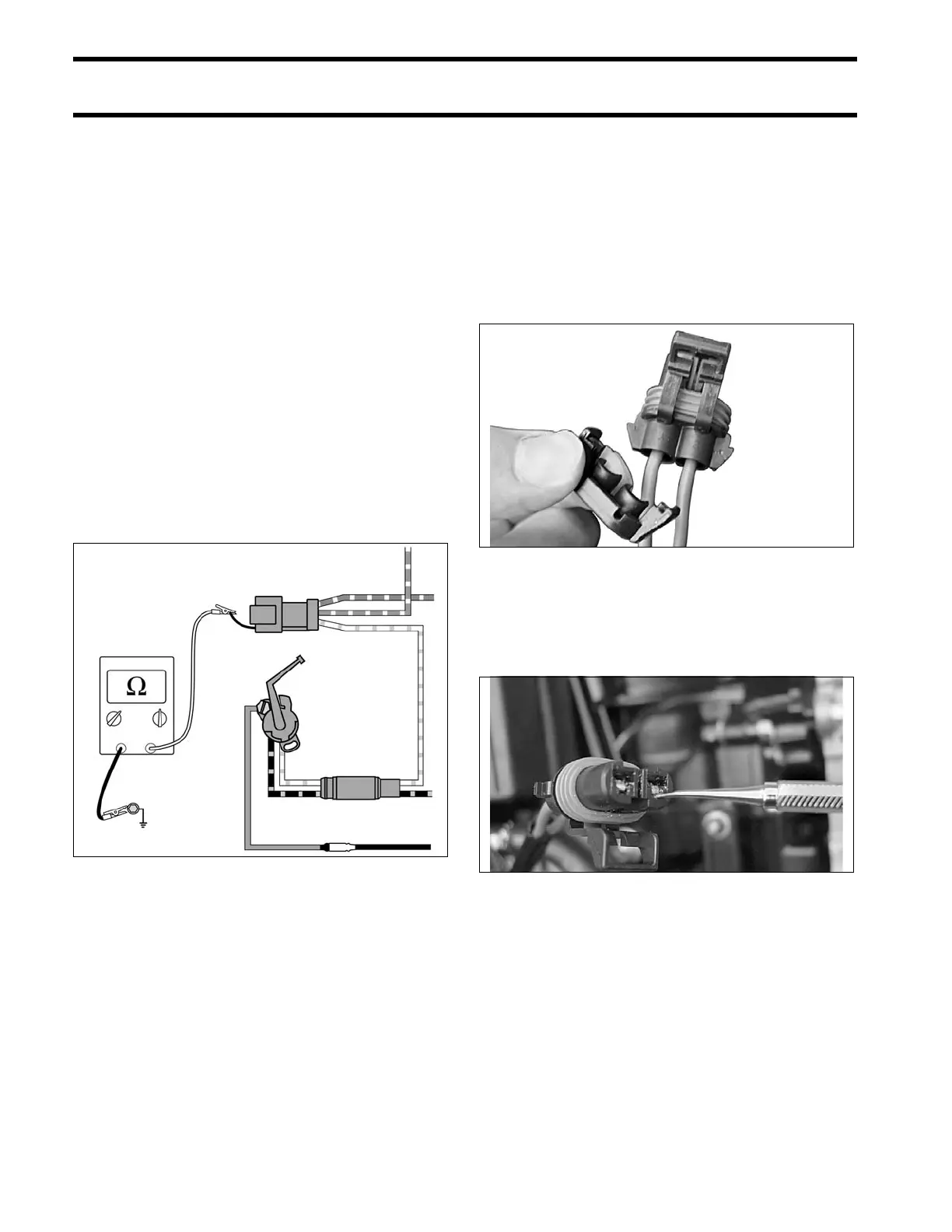
Remove the rubber grommet from the blue/green
trim/tilt cable connector.
Remove the terminals from the connector by
using a suitable tool to depress the tab. While the
tab is depressed, pull on the wire from the rear of
the connector to release it from the connector.
DRC6247
000686
000687