111
ELECTRICAL AND IGNITION
FLYWHEEL AND STATOR SERVICING
6
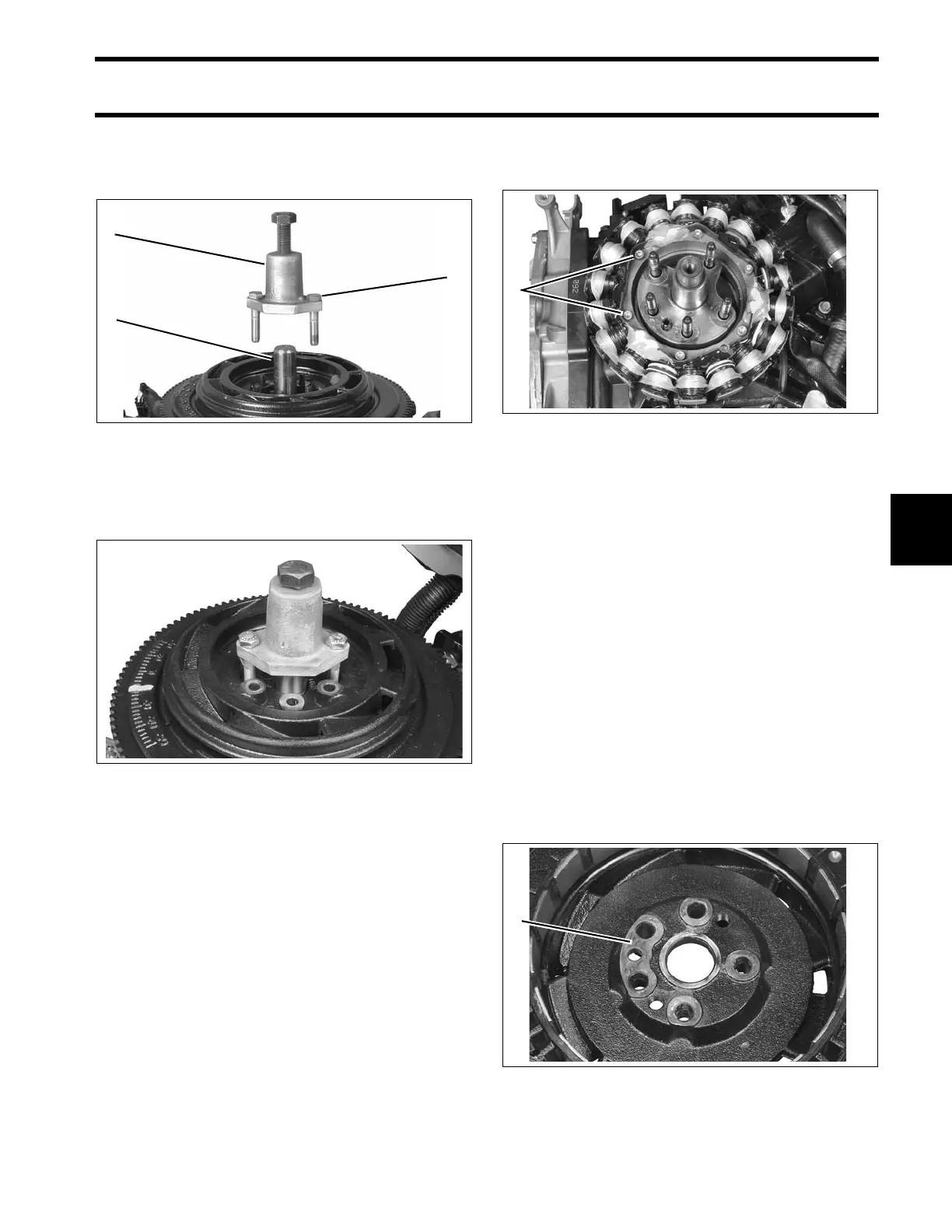
Use two 3/8-24x2 in. screws from the adaptor kit
to attach the tool to the flywheel. Two holes are
tapped in the flywheel for the tool.
Turn the center screw of the puller in to lift the fly-
wheel off of the crankshaft.
Stator Service
Remove six allen head screws to remove stator.
To install stator, position stator on cylinder block.
Apply Nut Lock to screw threads. Install screws
and tighten in crossing pattern to a torque of 24 to
36 in. lbs. (3 to 4 N·m).
Flywheel Installation
IMPORTANT: Check ignition timing after fly-
wheel removal or replacement. Refer to TIMING
ADJUSTMENTS on p. 114.
If studs must be replaced in crankshaft, apply
Ultra Lock to threads and tighten by hand, no
more than 48 in. lbs. (5.5 N·m).
Remove any debris from the flywheel magnets
and the flywheel and crankshaft mating surfaces.
Apply Nut Lock to the raised mounting bosses on
the bottom of the flywheel.
1. Puller
2. Bushing
3. Screws - 3/8 - 24 x 2 in. (2)
005369
005381
1. Stator screws 005382
1. Flywheel mounting bosses 005370