216
POWERHEAD
POWERHEAD ASSEMBLY
Start in the center and work outward in a spiral
pattern.
Apply Nut Lock to crankcase flange screws. Install
screws and tighten to a torque of 60 to 84 in. lbs.
(7 to 9.5 N·m).
Test that the crankshaft spins freely without bind-
ing.
IMPORTANT: After powerhead has been
assembled, allow at least two hours for Gel-Seal II
to cure before running outboard.
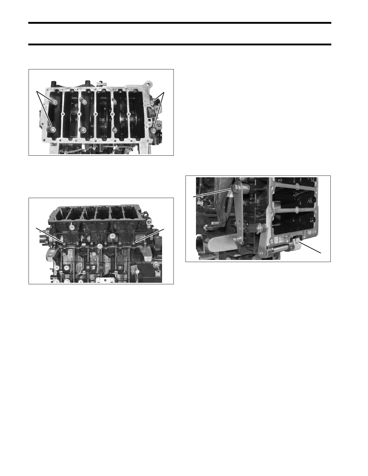
Shift Linkage Installation
Lubricate shift linkage bosses at the base of the
crankcase with Triple-Guard grease. Insert bush-
ings into bosses.
Apply Triple-Guard grease to the shaft of the shift
lever assembly. Guide shaft through bushings in
crankcase.
Apply Triple-Guard grease to shoulder of shift arm
screw and Nut Lock to threads. Install arm, screw,
and washer and tighten screw to a torque of 120
to 144 in. lbs. (13.5 to 16.5 N·m).
Install shift rod lever and tighten retaining screw
60 to 84 in. lbs. (7 to 9.5 N·m).
005313
005306
1. Shift arm screw
2. Shift lever screw
008454