21
ROUTINE SERVICE
OUTBOARD RIGGING CONNECTIONS
2
Use an I-Command Ignition and Trim Harness to
connect the outboard to the key switch and trim/tilt
control. Seal unused SystemCheck connector
with 6-Pin Connector Seal, P/N 586076.
If connecting to an existing I-Command Classic
network, connect the purple wires between the I-
Command Ignition and Trim Harness and the I-
Command Engine Interface Cable. This connec-
tion supplies power to the network when the key
switch is on. I-Command Digital networks do not
use this connection.
Route the harnesses around the starboard side of
the powerhead along the same path as the battery
cables.
Secure all cables with tie-straps.
For an I-Command oil level display, an accessory
CANbus oil level sender must be installed in the
oil tank. Connect the sender to the I-Command
network. Refer to the I-Command Digital Net-
work Guide.
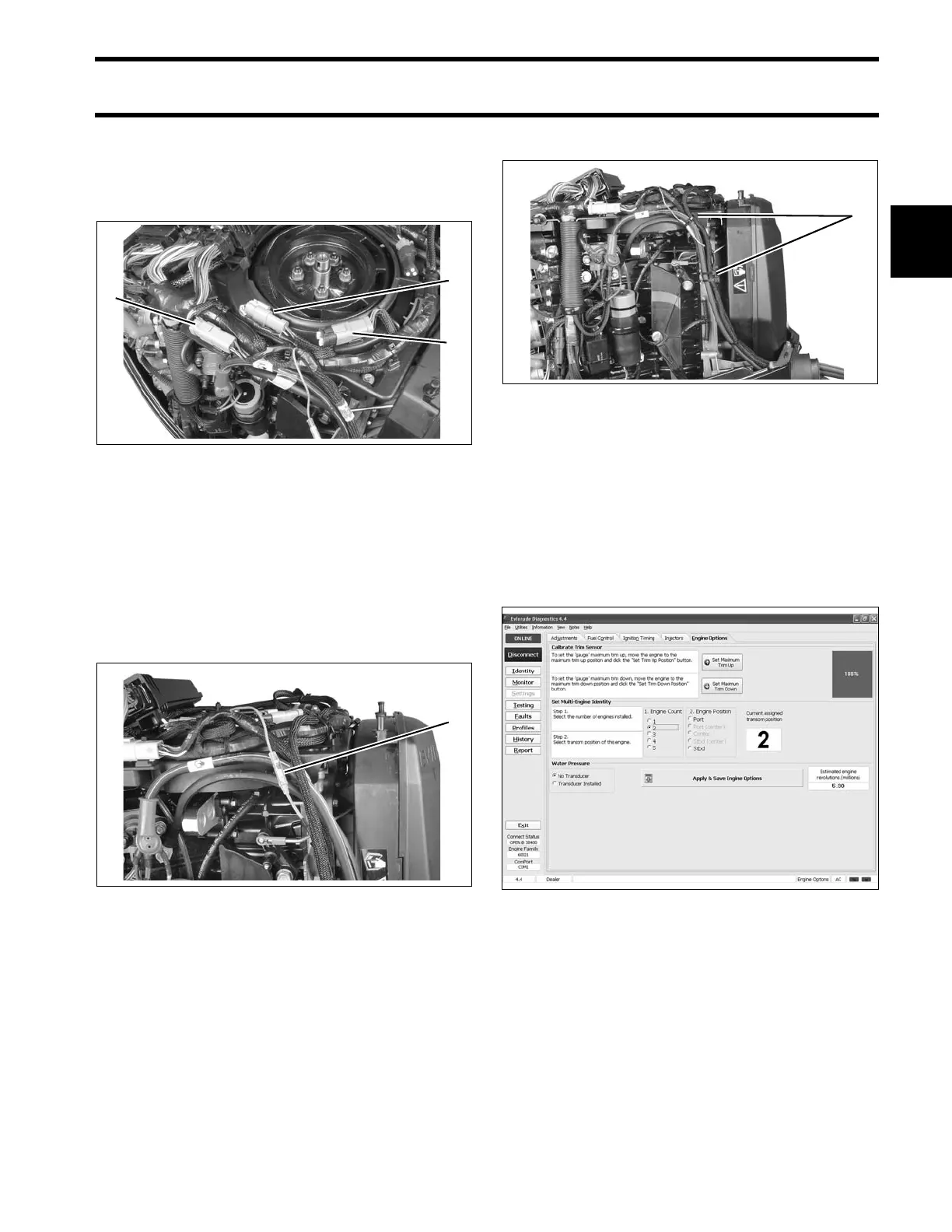
Use Evinrude Diagnostics software to adjust net-
work settings in the EMM. From the Settings
screen, select Engine Options.
1. CANbus Ignition connector
2. Trim/Tilt connector
3. SystemCheck connector (with seal)
005266
1. CANbus power supply connector 005269
1. Anchor points 005270
Engine Options Screen 008013