22 (93) BRUKER CryoProbe Installation
Initial setup
BCU05 cooling test (optional) 3.7
0
If a gas cooler, e.g. a BCU05, shall be used with a VT hose between its outlet and
the CryoProbe, its output temperature must be tested and adjusted. The goal is
that the VT gas enters the CryoProbe no colder than the lowest permitted sample
temperature. This temperature is specified on the CryoProbe’s L
IMITATIONS -
W
ARNINGS sheet. The test can be run conveniently while the CryoProbe System is
installed.
In the presence of an isolated VT gas port that is integrated with the Tuning
Adapter, this BCU05 cooling test can be skipped.
Spectrometer modifications 3.8
Remove any sample and conventional probe from the magnet. Close the magnet
bore temporarily to protect it against magnetic particles.
Access to the magnet bottom 3.8.1
A spatial channel of at least 195 ⌠ 578 (628) mm [width ⌠ height] is needed from
the magnet front to insert a 500 (600) MHz CryoProbe (see Site Planning Guide).
NOTE: A QNP pneumatic unit prevents the installation of a CryoProbe and must
be removed for the time of CryoProbe operation.
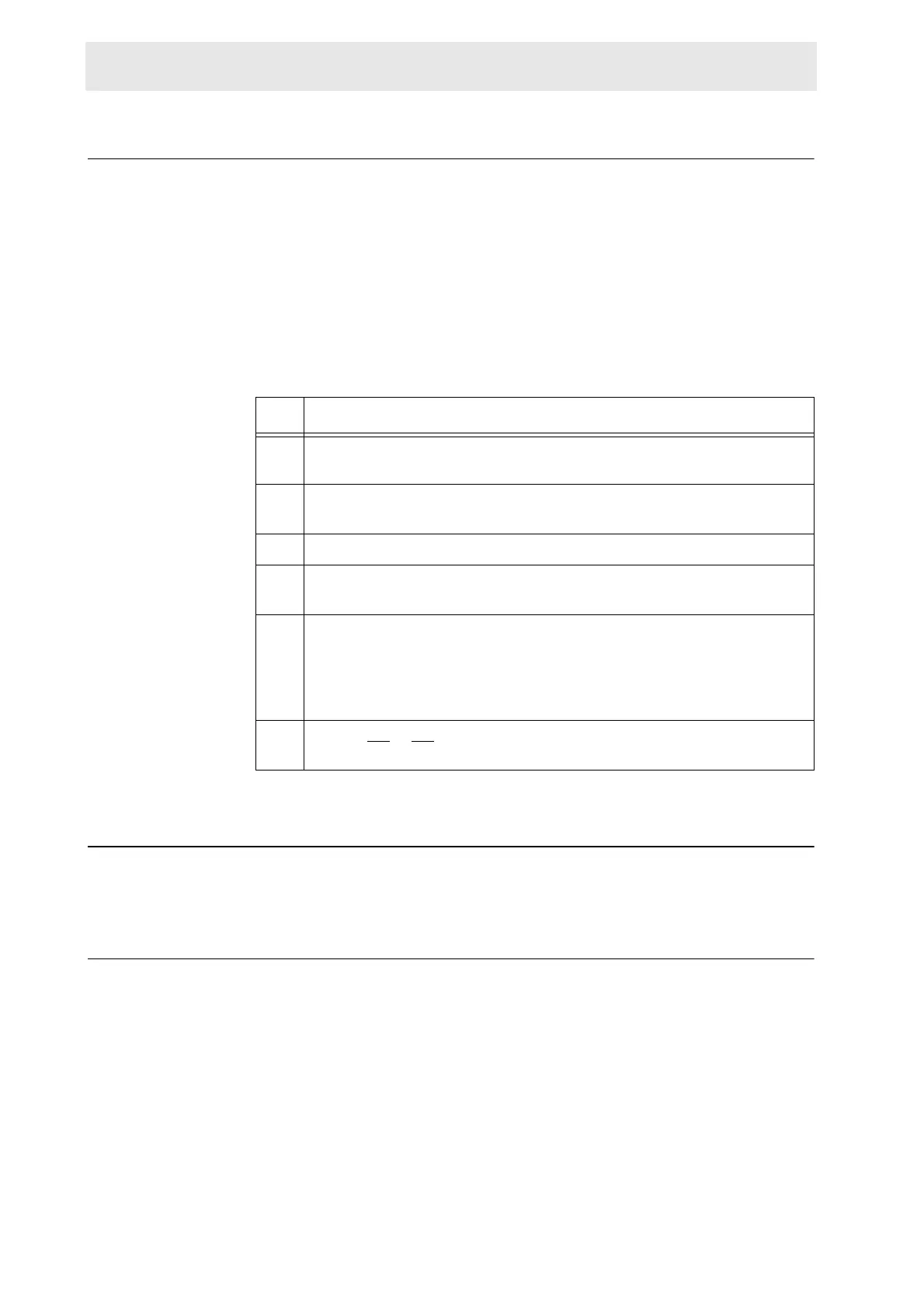
Table 3.2. Adjust the BCU05 outlet temperature
step action
b.1 Connect the spherical adapter of the CryoProbe VT hose to the BCU05
gas outlet but do not connect the VT hose to the CryoProbe.
b.2 Set the gas flow rate to the minimum value specified on the Cryo-
Probe’s L
IMITATIONS - WARNINGS sheet (e.g. 600 L/h).
b.3 Switch ON the BCU05.
b.4 After about 1 h, the BCU05 will have reached its operating temperature
and part of the CryoProbe VT hose will be covered with ice.
b.5 Shorten the VT hose from its 4 mm end such that its outlet is just not
frozen or moist.
NOTE: Keep at least 10 cm of the 4 mm tube! If necessary, continue to
chop off at the 8 mm tube.
b.6 Repeat b.4
to b.5 until the 4 mm outlet of the VT hose is just not fro-
zen.

 Loading...


