48 (93) BRUKER CryoProbe Installation
Initial setup
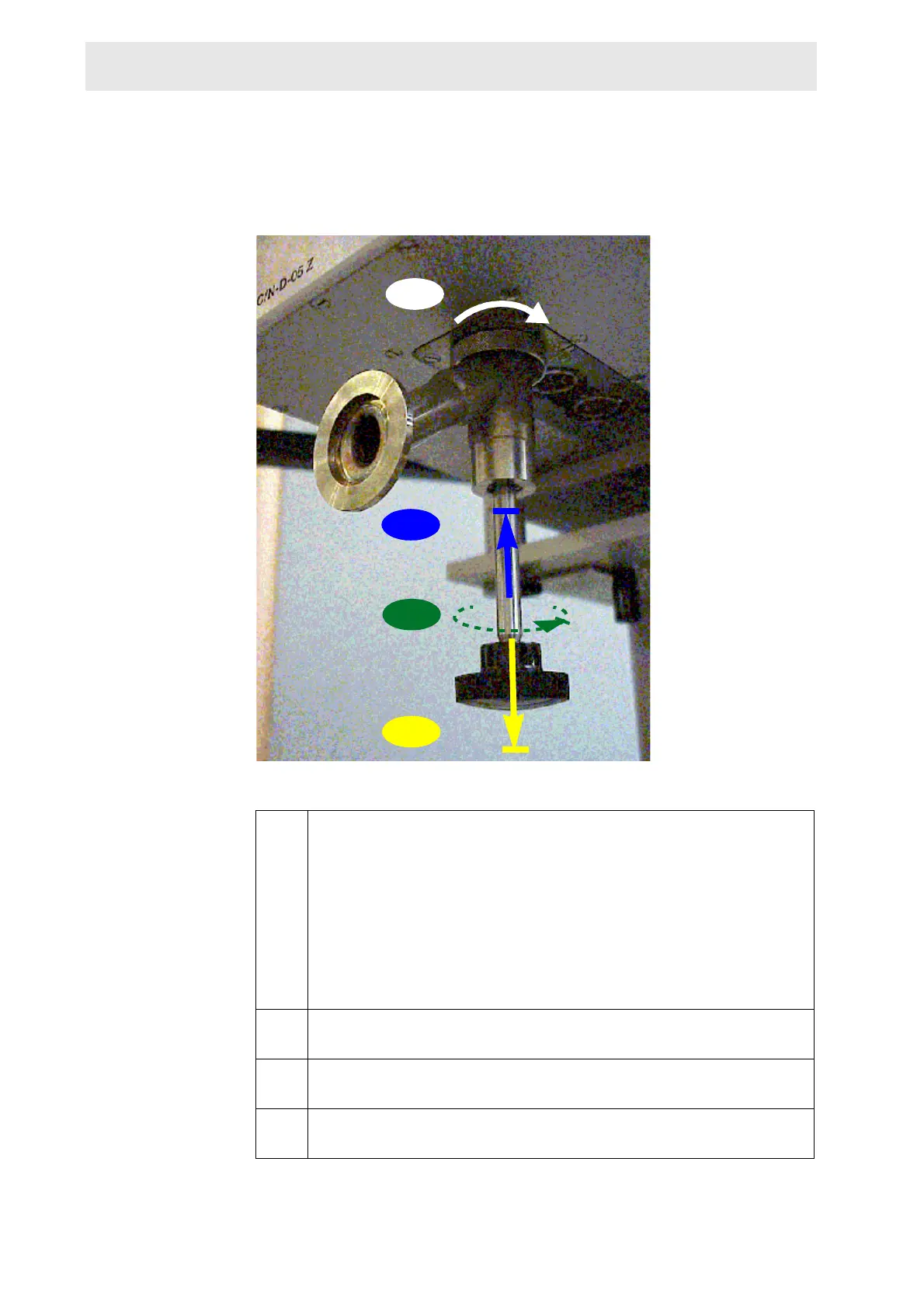
j.7 Draw out the CryoProbe’s actuator screw by at least 5 cm (2 inch) until
a stop is reached, thereby taking the vacuum plug out of the Cryo-
Probe.
NOTE: The vacuum system will be activated later.
If you doubt that the vacuum plug was fully taken out, you may
unmount the Vacuum Adaptor from the CryoProbe and the vacuum
tube for a visual inspection. Contact to air will not spoil the CryoProbe’s
vacuum chamber.
j.8 Connect the remaining RF and gradient cables (for details, see Cryo-
Probe RF Electronics Technical Manual).
j.9 Regulate the VT gas flow rate to (at least) the value specified on the
L
IMITATIONS - WARNINGS sheet.
j.10 Set the VT heater power limit as given on the LIMITATIONS - WARNINGS
sheet.
Figure 3.15. Open the CryoProbe vacuum plug
j.4
j.5
j.6
j.7
 Loading...


