EasyManuals Logo

Bruker CryoProbe System User Manual

Bruker CryoProbe System
93 pages
To Next Page IconTo Next Page
To Previous Page IconTo Previous Page
Page #35 background imageLoading...
Page #35 background image
Joining the CryoCoupler
CryoProbe Installation BRUKER 35 (93)
Figure 3.8. Unlock the vaccum flange screws
j.3 Remove the protective caps from the CryoCouplers on He Transfer-
line and CryoProbe.
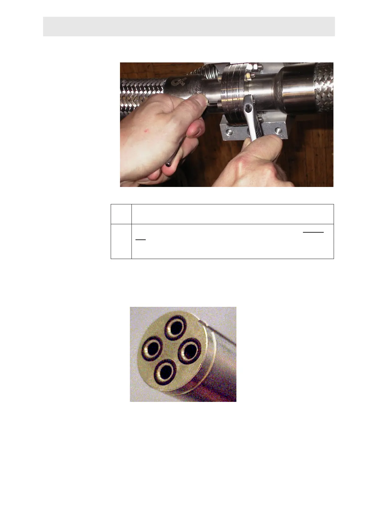
j.4 Check the four o-rings on the He Transferline CryoCoupler (Figure
3.9.): are they in place, clean and undamaged? If not replace with the
o-rings found in the spare parts box delivered with each CryoProbe
System. The o-rings are of type viton and size 7.1 by 1.6 mm.
Figure 3.9. O-rings on the CryoCoupler

Table of Contents

Questions and Answers:

Question and Answer IconNeed help?

Do you have a question about the Bruker CryoProbe System and is the answer not in the manual?

Bruker CryoProbe System Specifications

General IconGeneral
BrandBruker
ModelCryoProbe System
CategoryLaboratory Equipment
LanguageEnglish

Related product manuals