Home
Bruker
Laboratory Equipment
minispec
Bruker minispec User Manual
5
of 1
of 1 rating
82 pages
Give review
Manual
Specs
To Next Page
To Next Page
To Previous Page
To Previous Page
Loading...
Installation
30
H148850_3_003
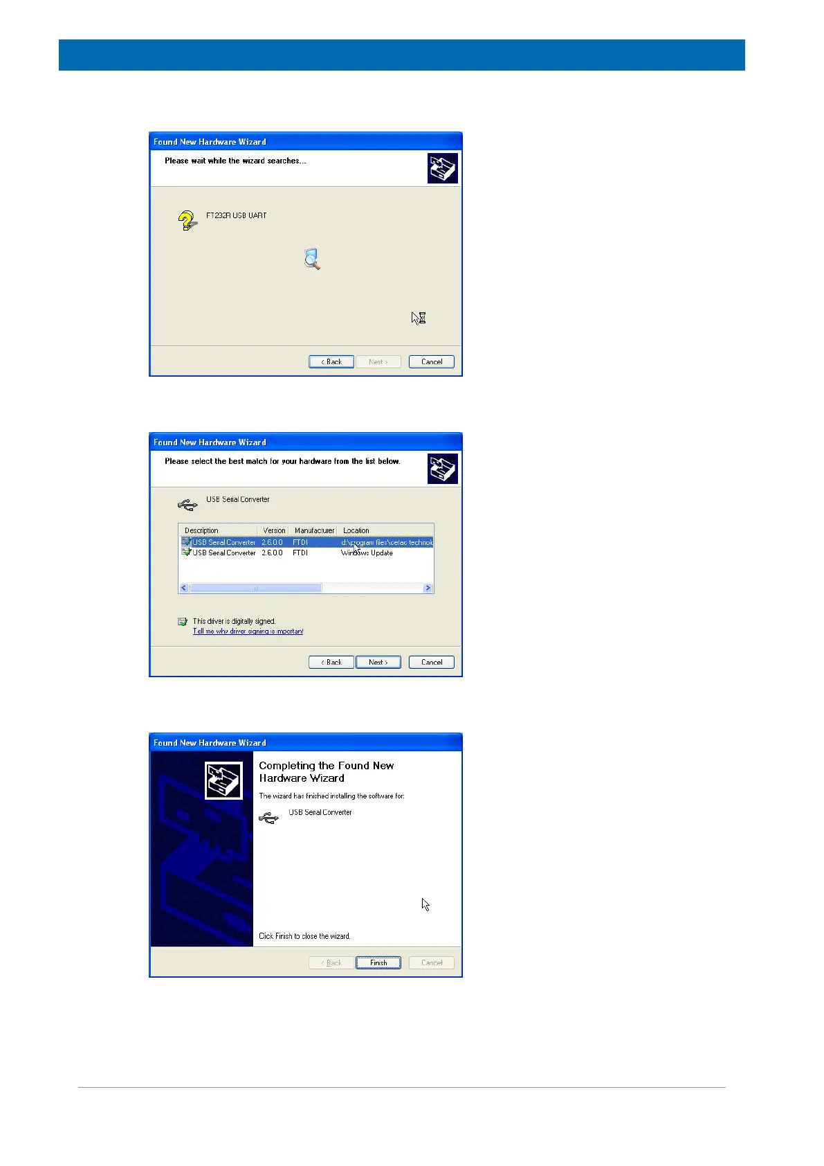
•
Wait while the computer searches the media.
Figure6.10: Searching for the Driver
•
When the driver is found, select it and click
Next
.
Figure6.11: Selecting the Driver
•
The driver installation is complete.
Figure6.12: Driver Installation is Complete
29
31
Table of Contents
Table of Contents
3
1 About this Manual
7
Policy Statement
7
Symbols and Conventions
7
2 Introduction
9
Overview
9
Who Should Read this Book
9
Intended Use
9
Where to Go for more Information
9
3 Safety
11
Safety Notices
11
Power Cord Set Requirements
11
Power Cord Safety Maintenance
11
Mains Disconnect
11
Operating Environment
12
Mechanical Hazards
13
Figure 3.1: Overview of the Mechanical Hazards (Without Optional Safety Barrier)
13
Figure 3.2: Overview of the Mechanical Hazards (with Optional Safety Barrier)
13
Explanation of Caution and Warning Notices
14
Electromagnetic Interference
14
Explanation of Regulatory Marks
15
Location of the Emergency Stop Button
15
Figure 3.3: E-Stop Button
15
4 Design and Function
17
Sample Changer Components
17
Figure 4.1: Sample Automation XYZ Sample Changer-Front View with TC3
17
Figure 4.2: Sample Automation XYZ Sample Changer-Front View with TC3 (2 Zone 26 MM Version) and Sample Stage
18
Additional Equipment Required
19
Figure 4.3: Sample Automation XYZ Sample Changer-Back View of Sample Changer Head
19
Optional Accessories
20
Chemical Compatibility
20
Figure 4.4: TC3 and TC6 Temperature Units
20
5 Transport, Packaging and Storage
21
6 Installation
23
Preparing for Installation
23
Choosing a Location
23
Space Requirements
24
Work Surface Requirements
24
Power Requirements
24
Table 6.1: Physical Characteristics
24
Table 14.2: Power Requirements
24
Installing the Temperature Units
25
Mounting the NMR Instrument
25
Connecting the E-Stop Button
25
Figure 6.1: Mounting Bracket
25
Without the Safety Barrier
26
Figure 6.2: E-Stop Shown on Left Side of the Base
26
Figure 6.3: Location of Holes in the Bracket
26
Figure 6.4: Location of Mounting Screws
26
With the Safety Barrier
27
Figure 6.5: Rear View of E-Stop after Mounting (Shown Mounted to Safety Barrier so that Screw Locations Are more Visible)
27
Figure 6.6: E-Stop Connected to the Sample Changer
27
Connecting the Sample Changer to the Power Supply
28
Connecting the Sample Changer to the Host Computer
28
Establishing a USB Communications Interface
28
Figure 6.7: Message Showing that a Driver was Not Found
29
Figure 6.8: Choosing to Install USB Driver
29
Figure 6.9: Choosing to Install USB Driver from a Removable Media
29
Figure 6.10: Searching for the Driver
30
Figure 6.11: Selecting the Driver
30
Figure 6.12: Driver Installation Is Complete
30
Establishing an RS-232 Serial Communications Interface
31
Verifying Installation
31
Aligning the Sample Changer
32
Testing the Gripper
32
7 Safety Barrier Assembly Installation (Optional)
33
Preparing the Sample Changer
33
Safety Barrier Assembly
33
8 Operation
43
Establishing Optimal Operating Conditions
43
Purchasing Supplies
44
Starting the Sample Changer
44
Stopping Sample Changer Movement
45
Shutting down the Sample Changer
45
Using the Safety Barrier
45
Figure 8.1: E-Stop Button
45
Opening the Safety Barrier
46
Figure 8.2: Safety Barrier Latch
46
9 Sample Stage
47
Figure 9.1: Sample Stage (10 MM Version Shown)
47
Installing the Sample Stage
48
Unpacking the Sample Stage
48
Setting the Address for Dual Sample Stage Applications
48
Figure 9.2: Opening on the Bottom of the Sample Stage
49
Figure 9.3: Address Dial
49
Figure 9.4: Dual Sample Stage Addresses-26 MM
50
Figure 9.5: Dual Sample Stage Addresses-10 MM
50
Installing the Sample Stage on the Base
51
Figure 9.6: Base of the Sample Changer
51
Connecting the Data Cables
52
Connecting to a Power Source
52
Figure 9.7: Serial Connector on the Sample Stage
52
Figure 9.8: Power Supply
52
Operating the Sample Stage
53
Figure 9.9: Power Connections for the Sample Stage
53
10 Maintenance
55
Cleaning the Sample Changer
55
Daily External Cleaning
55
Weekly Cleaning
56
Cleaning the Safety Barrier
56
Mounting the Z-Drive Assembly
57
Tools Required
57
Figure 10.1: Positioning the Carriage
57
Figure 10.2: Sliding the Z-Drive Onto the Y-Arm
58
Figure 10.3: Attaching the Z-Drive to the Carriage
58
Figure 10.4: Attaching the Z-Drive Strain Relief Block
59
Figure 10.5: Connecting the Z-Drive Cable
59
Using Tubing Tamers
60
Figure 10.6: Connecting Tubing Tamer
60
Figure 10.7: Tubing Tamer Properly Installed on Z-Drive Cable
60
Connecting the Pneumatic Tubing
61
Connecting the Auxiliary Connector
62
11 Troubleshooting
63
Power System Problems
63
Communications Interface Problems
64
USB Cable Problems
64
12 Replacement of Parts
65
Returning the Unit for Repair
65
13 Dismantling and Disposal
67
Dismantling
67
Disposal Europe
67
Disposal USA and Other Countries
68
14 Technical Data
69
Environmental Characteristics
69
Table 14.1: Environmental Characteristics
69
Electrical Characteristics
70
Power Requirements
70
Data Connectors - Sample Changer
71
Data Connectors - Temperature Units
71
Pneumatic Connections
71
Table 14.3: Data Connectors on the Sample Changer
71
Table 14.4: Data Connectors - Temperature Units
71
15 Contact
73
List of Figures
75
Index
79
5
Based on 1 rating
Ask a question
Give review
Questions and Answers:
Need help?
Do you have a question about the Bruker minispec and is the answer not in the manual?
Ask a question
Bruker minispec Specifications
General
Brand
Bruker
Model
minispec
Category
Laboratory Equipment
Language
English
Related product manuals
Bruker minispec mq20
86 pages
Bruker BCU05
41 pages
Bruker HPPR/2
92 pages
Bruker BSMS/2
61 pages
Bruker BPHG 90
78 pages
Bruker NMR CASE
15 pages
Bruker IFS 125M
228 pages
Bruker DektakXT
83 pages
Bruker CryoProbe
107 pages
Bruker AVANCE NEO
120 pages
Bruker 700'54 Ascend
100 pages
Bruker NMR AVANCE NEO Systems
48 pages