Installation
H148850_3_003 27
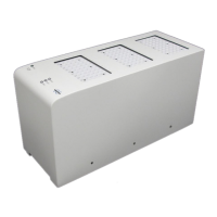
• Install the two nuts on the mounting screws.
Figure6.5: Rear View of E-Stop After Mounting (shown mounted to safety barrier so that screw locations
are more visible)
• Replace the front of the button enclosure.
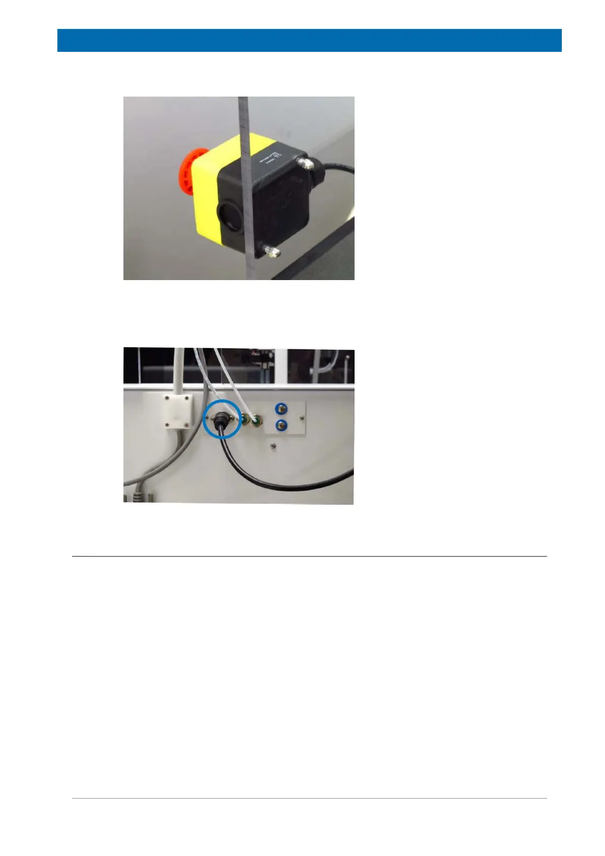
• Connect the button to the back of the sample changer.
Figure6.6: E-stop Connected to the Sample Changer
6.4.2 With the Safety Barrier
The e-stop button is installed when the safety barrier is assembled. See the Safety Barrier
Assembly Quick Installation Guide.
Connect the button to the back of the sample changer, as shown in Figure 6.6 [}27].