Design and Function
H148850_3_003 17
4 Design and Function
4.1 Sample Changer Components
The following components are located on the front of the sample changer and are shipped
with the sample changer.
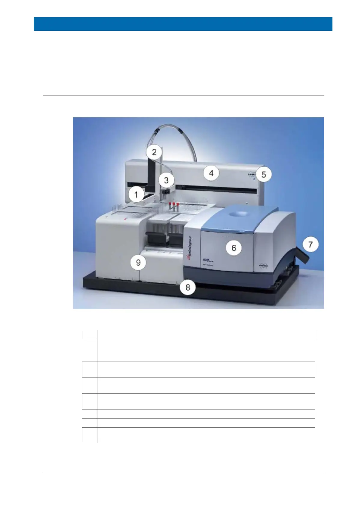
Figure4.1: Sample Automation XYZ Sample Changer—Front View with TC3 (10 mm SFC Version), TC6
and MFC Analyzer
1 Arm: The arm moves the gripper horizontally
2 Z-Drive Assembly: The Z-Drive assembly moves the gripper vertically. The
assembly includes a Z-Axis motor assembly as well as the gripper mounting
bracket. The Z-Drive motor assembly attaches onto the sample changer arm.
3 Gripper Assembly: The pneumatic gripper assembly moves vials between the
temperature units and the instrument.
4 Sample Changer Head: The sample changer head contains electronics for the
sample changer and supports the sample changer arm.
5 Power Indicator Lamp: The LED indicates that the sample changer is
connected to a power source and turned on.
6 NMR Instrument: The instrument to which the sample changer is connected.
7 Waste Chute: The sample changer can drop used vials here for disposal.
8 Base: The temperature units and the NMR instrument attach securely to the
base of the sample changer.