System Description VÅNTEC-1 Detector User Manual
3 - 18 M88-E01072
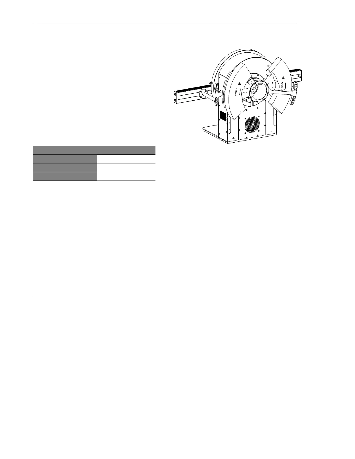
3.5 Counterbalance
The counterbalance is located on the back of
the goniometer. Figure 3.16 shows an example
of a counterbalance on a θ/θ goniometer. The
addition of a counterbalance provides smooth
and flawless movement of the goniometer. The
position of the counterbalance is based on the
weight of the detector and optics, the measuring
circle diameter, and the height of the sample
stage. In order to ensure proper weight distribu-
tion, please use the tables below to select the
correct position of the counterbalance for the
detector system. Table 3.3 refers to the posi-
tions shown in Figure 3.17.
Figure 3.16 - Counterbalance on the goniometer
Stage Height (mm)
150 214 258
Circle Diameter (mm)
435 500 600
Handle
-4 -1 1
Weight
BBB
Table 3.3 – Position of the handle and weight for the
counterbalance